You are using an out of date browser. It may not display this or other websites correctly.
You should upgrade or use an alternative browser.
You should upgrade or use an alternative browser.
Building an Inertia/Kinetic Splitter
- Thread starter bower4311
- Start date


Help Support Arborist Forum:
This site may earn a commission from merchant affiliate
links, including eBay, Amazon, and others.
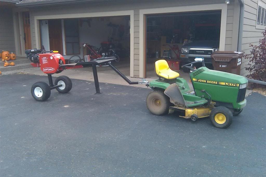
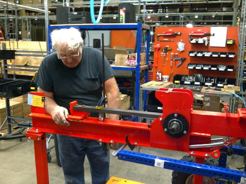
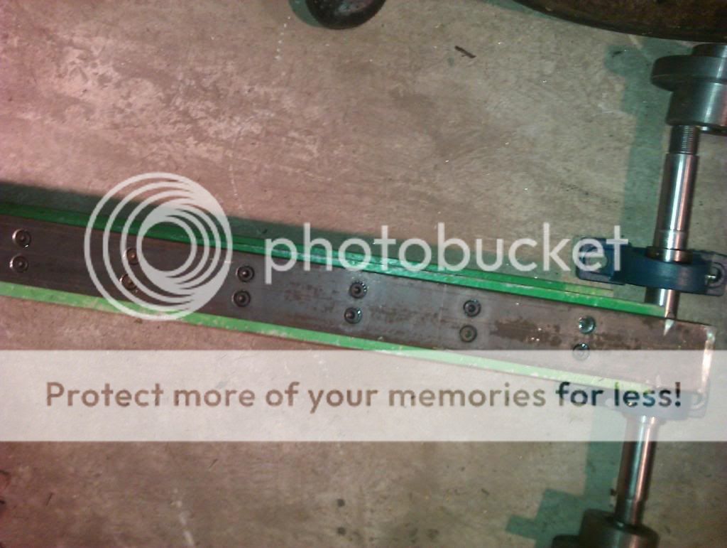
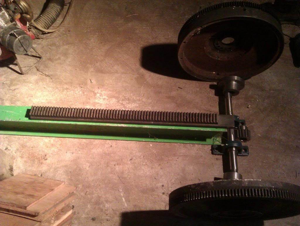
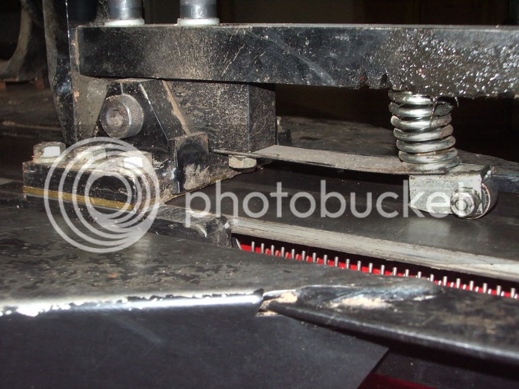
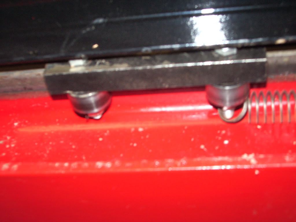
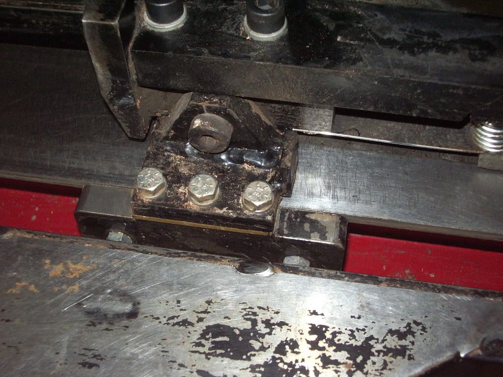
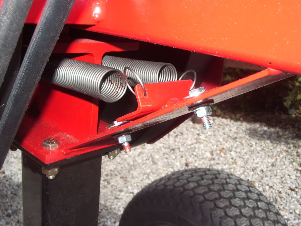
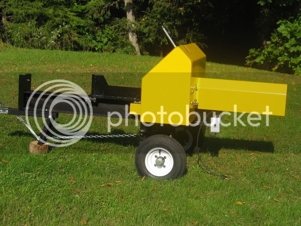
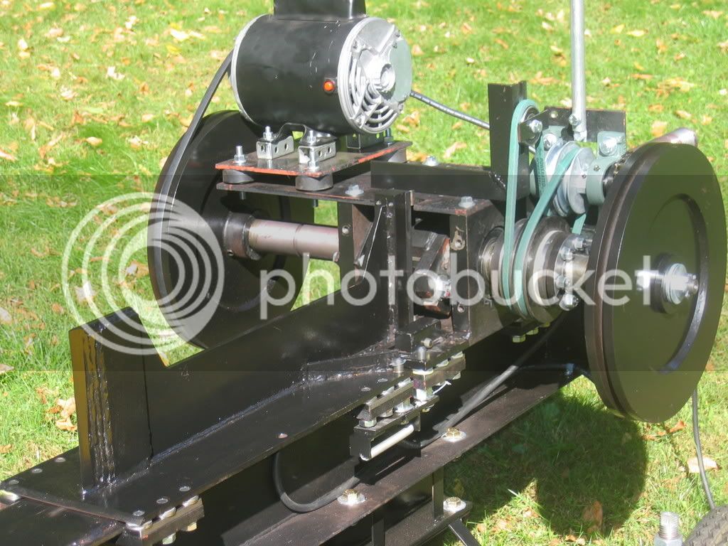
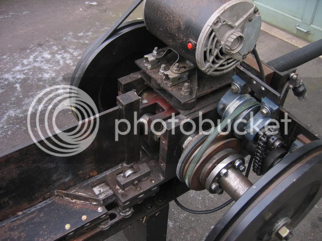
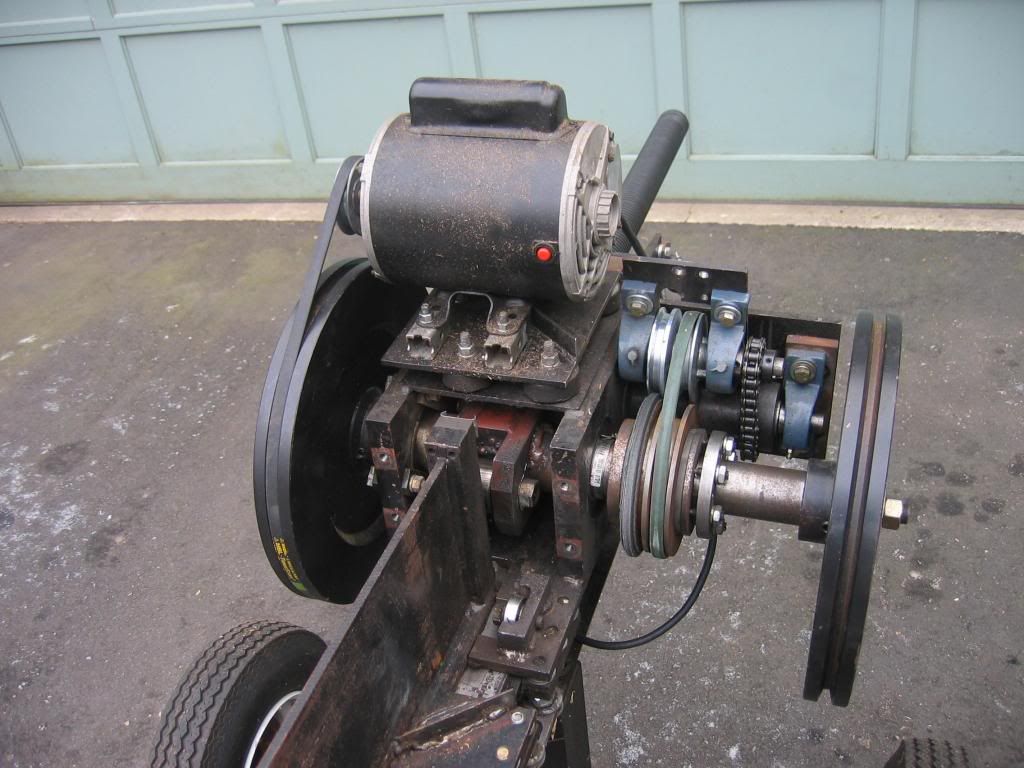
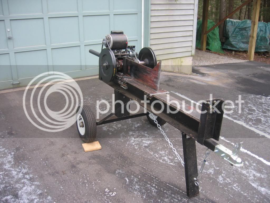
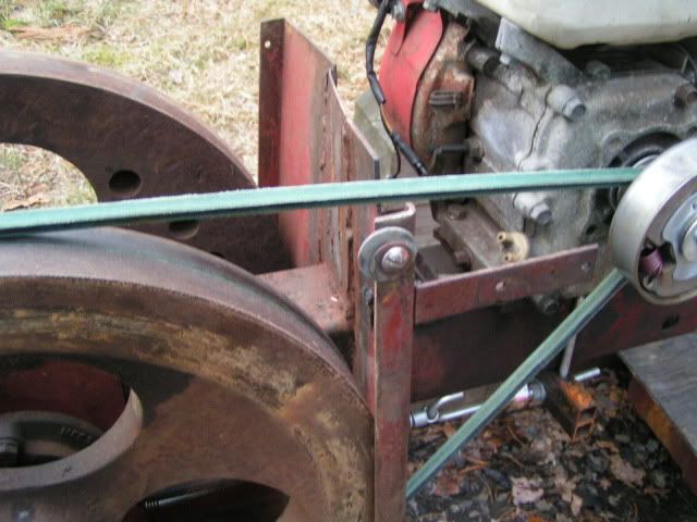
here is a quick couple pictures of mine. please note this is just kinda mocked up for now.
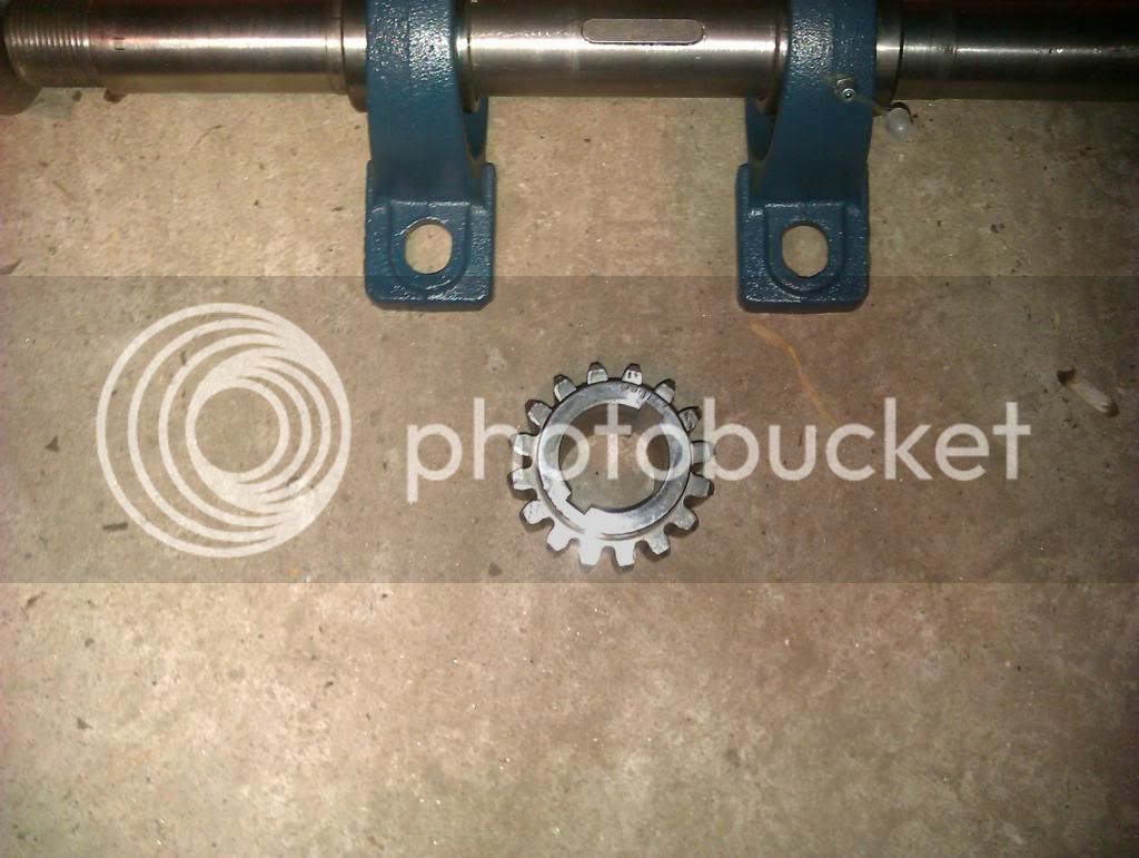
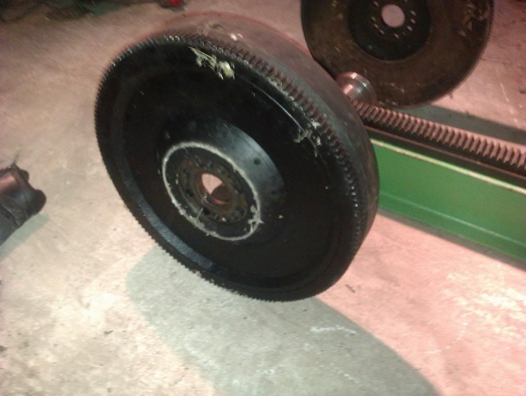
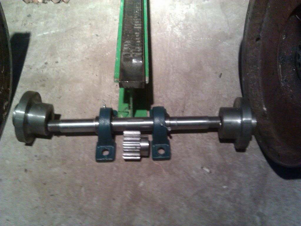
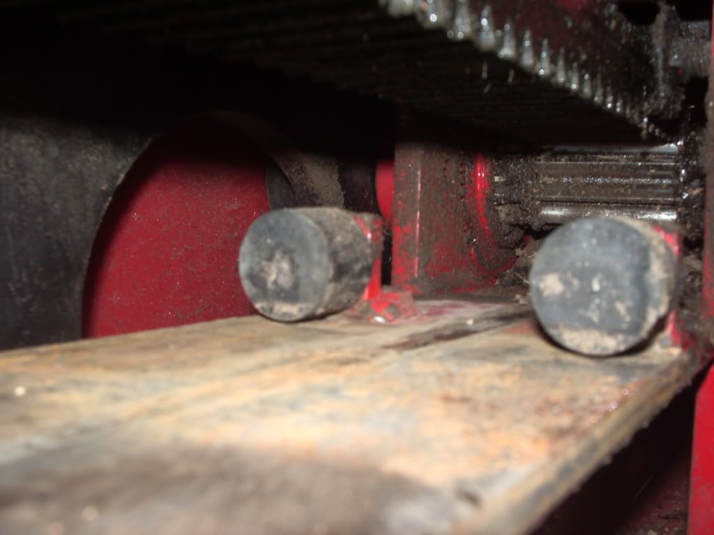
Where did you get the flywheels. Whats there size and weight? How many teeth are on that pinion gear??
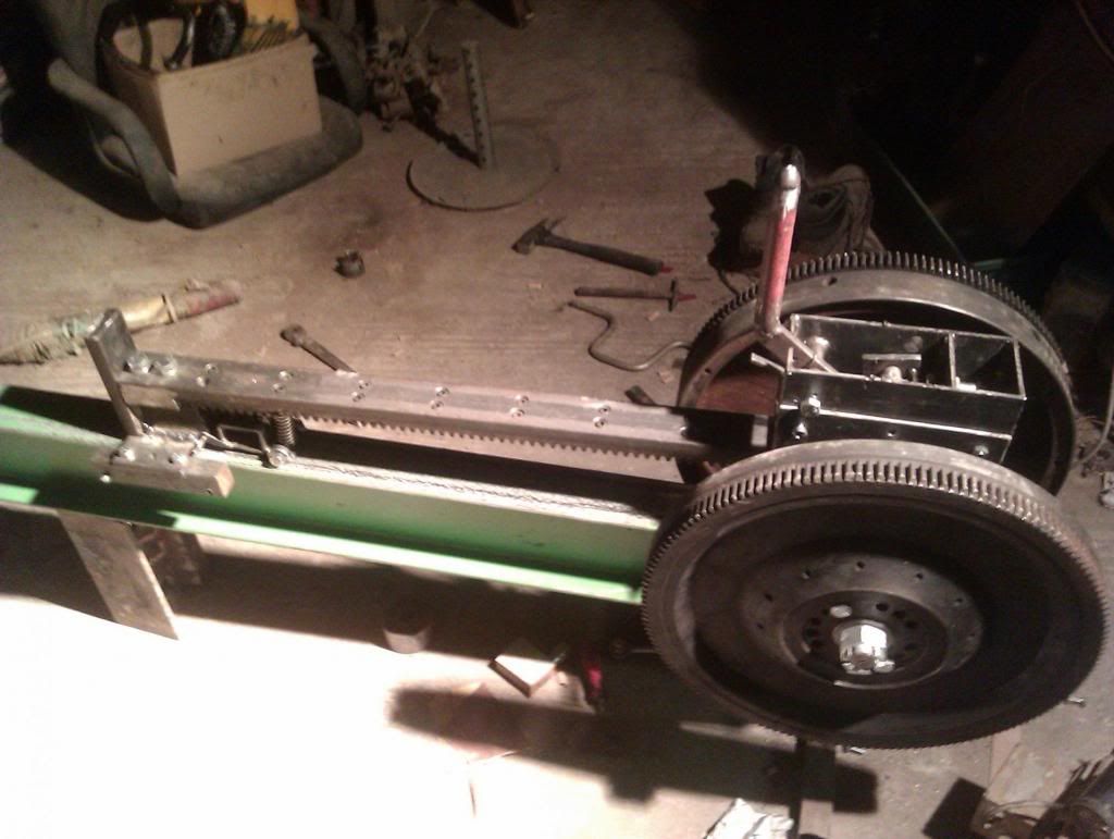
the gear is 14.5 21 tooth
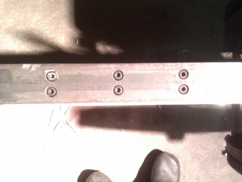
the flywheels i cnc plasma cut from 1 inch carbon steel and had a machinist friend turn them down and broach a keyway
the shaft is 1-3/8'' fully keyed non hardened carbon from mcmaster carr.
the flywheels i cnc plasma cut from 1 inch carbon steel and had a machinist friend turn them down and broach a keyway
the shaft is 1-3/8'' fully keyed non hardened carbon from mcmaster carr.
the gear is 14.5 21 tooth
the flywheels i cnc plasma cut from 1 inch carbon steel and had a machinist friend turn them down and broach a keyway
the shaft is 1-3/8'' fully keyed non hardened carbon from mcmaster carr.
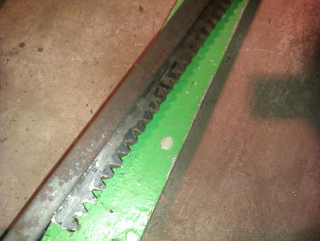
The only problem I see is the 21 tooth gear. You are going to have to really slow down the shaft that the sprocket is mounted to or the rack is really going to rocket out. Most builds use a 15 tooth and I think Supersplit machines 12 teeth onto a shaft. With a 15 tooth gear about the largest shaft you can mount it on is 1 1/4". This is another issue with this design.
bower4311
ArboristSite Operative
The only problem I see is the 21 tooth gear. You are going to have to really slow down the shaft that the sprocket is mounted to or the rack is really going to rocket out. Most builds use a 15 tooth and I think Supersplit machines 12 teeth onto a shaft. With a 15 tooth gear about the largest shaft you can mount it on is 1 1/4". This is another issue with this design.
Right. Now this is where it has been said to have the pinion gear bored to accept a bigger shaft? 1/8th bigger to 1-3/8?
bower4311
ArboristSite Operative
yes i hear you on the number of teeth. the reason i went with this set up is i got the rack and pinion free and started from there.
Can't beat that. You'll have to let us know how it goes.
When do you plan on working on the splitter some more?
A couple random thoughts on potential issues that were discussed a couple pages back...
For the gear/rack meshing, I think that by keeping the shaft speed relatively low (something in the 300rpm range) and using gears that are generously oversize for your loads, you really should be fine. No, it's certainly not the "ideal" way to do things, but you're also generally working at much lower loads, speed and cycles than these gears are capable of.
The big challenge that I see is getting the right compromise in your gear selection so that everything is strong enough, but your ram speed isn't too crazy fast.
Assume you have your flywheels spinning at 300RPM and rigidly attached to the gear shaft (so it's at 300 RPM as well).
If you were to go with a very low pitch gear in order to have a larger diameter through shaft, you end up with a ram speed that's too high. But, in order to slow that down, your gear pitch has to increase which decreases the diameter of the gear for a given number of teeth (increasing the number of teeth will increase ram speed again). So your through shaft gets smaller. The question then becomes can you find a compromise that gives an acceptable (i.e. semi safe) ram speed and a strong enough shaft. Looking at the DR splitter, they accomplish that by custom machining the gear teeth into the shaft so that their shaft OD matches the gear OD. But that's a bit out of the realm of the home builder...
Looking at an 8P, 15T gear at 300 RPM, I'm getting a ram speed of about 29"/sec. That seems s bit higher than you'd want. (appologies if my calcs are off, it's been a long day, so I may be doing something stupid here...). The problem is that it's a bit of a challenge to get the gear size down much further. I'm thinking you wouldn't want much less than a 1" dia. shaft and it's going to be hard to get much smaller a gear on that size shaft - at least using a keyway or something like that.
So, a few options.
1) Use a gear with no keyway and weld it to the shaft. That'll let you get a bit smaller on the gear. It's going to cause some issues with a heat treated gear or shaft though although you might not need that.
2) Put the flywheels on a separate shaft and use a gear, belt, etc... to slow down the shaft that your final gear is on. That would also allow you to increase the flywheel speed a bit which helps as the momentum that drives the whole thing is a function of the speed squared but only linear with mass. Just remember that the faster the flywheels go, the better balanced they need to be.
I actually kind of like the second option - especially if you could get enough force out of a belt drive on the speed reduction as belt slip would give you a fuse in the system to protect everything else. It might be too much of a fuse though and also protect the wood you're trying to split!
Lots of options!
A couple random thoughts on potential issues that were discussed a couple pages back...
For the gear/rack meshing, I think that by keeping the shaft speed relatively low (something in the 300rpm range) and using gears that are generously oversize for your loads, you really should be fine. No, it's certainly not the "ideal" way to do things, but you're also generally working at much lower loads, speed and cycles than these gears are capable of.
The big challenge that I see is getting the right compromise in your gear selection so that everything is strong enough, but your ram speed isn't too crazy fast.
Assume you have your flywheels spinning at 300RPM and rigidly attached to the gear shaft (so it's at 300 RPM as well).
If you were to go with a very low pitch gear in order to have a larger diameter through shaft, you end up with a ram speed that's too high. But, in order to slow that down, your gear pitch has to increase which decreases the diameter of the gear for a given number of teeth (increasing the number of teeth will increase ram speed again). So your through shaft gets smaller. The question then becomes can you find a compromise that gives an acceptable (i.e. semi safe) ram speed and a strong enough shaft. Looking at the DR splitter, they accomplish that by custom machining the gear teeth into the shaft so that their shaft OD matches the gear OD. But that's a bit out of the realm of the home builder...
Looking at an 8P, 15T gear at 300 RPM, I'm getting a ram speed of about 29"/sec. That seems s bit higher than you'd want. (appologies if my calcs are off, it's been a long day, so I may be doing something stupid here...). The problem is that it's a bit of a challenge to get the gear size down much further. I'm thinking you wouldn't want much less than a 1" dia. shaft and it's going to be hard to get much smaller a gear on that size shaft - at least using a keyway or something like that.
So, a few options.
1) Use a gear with no keyway and weld it to the shaft. That'll let you get a bit smaller on the gear. It's going to cause some issues with a heat treated gear or shaft though although you might not need that.
2) Put the flywheels on a separate shaft and use a gear, belt, etc... to slow down the shaft that your final gear is on. That would also allow you to increase the flywheel speed a bit which helps as the momentum that drives the whole thing is a function of the speed squared but only linear with mass. Just remember that the faster the flywheels go, the better balanced they need to be.
I actually kind of like the second option - especially if you could get enough force out of a belt drive on the speed reduction as belt slip would give you a fuse in the system to protect everything else. It might be too much of a fuse though and also protect the wood you're trying to split!
Lots of options!
I couldn't have said it better myself. I believe 300 rpm is the very high side and something around 200 rpm would be better. It also seems that the bigger and heavier the flywheels the more slower you can turn the pinion (better and easier on the rack and gear) and still have the intertia to split the wood. Like you said, when you start getting the pinion gear smaller you lose useable shaft size that the pinion gear mounts on. I know Supersplit and now you said DR machines teeth right on the shaft to get around this problem. I think this is the single most important design feature of having a successful inertia splitter (keeping the pinion gear shaft speed down around 200 rpm).
The engagement itself only has to overcome the inertia of the ram (usually on rollers)so it is a factor, but I think more important is the speed and danger of a tough log poping up off the wedge. It remains to be seen, but I think small shaft sizes are going to lead to shearing problems. Speaking of shearing, hay balers use shear bolts on the flywheel to protect the gearbox from solid objects in the plunger case.
bower4311
ArboristSite Operative
Well we've heard a lot of different opinions. I've compiled a bunch of pictures I'll upload tomorrow sometime. It will make this thread pretty picture heavy.
Sent from my Galaxy Nexus using Tapatalk 2
Sent from my Galaxy Nexus using Tapatalk 2
bower4311
ArboristSite Operative
bower4311
ArboristSite Operative
bower4311
ArboristSite Operative
bower4311
ArboristSite Operative
bower4311
ArboristSite Operative
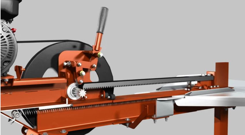
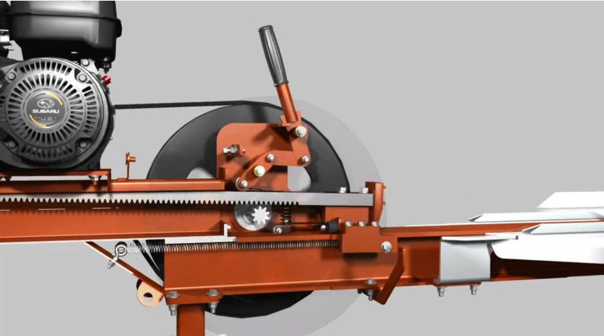
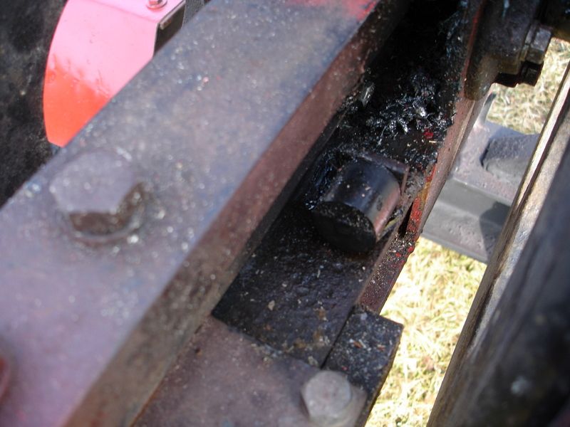
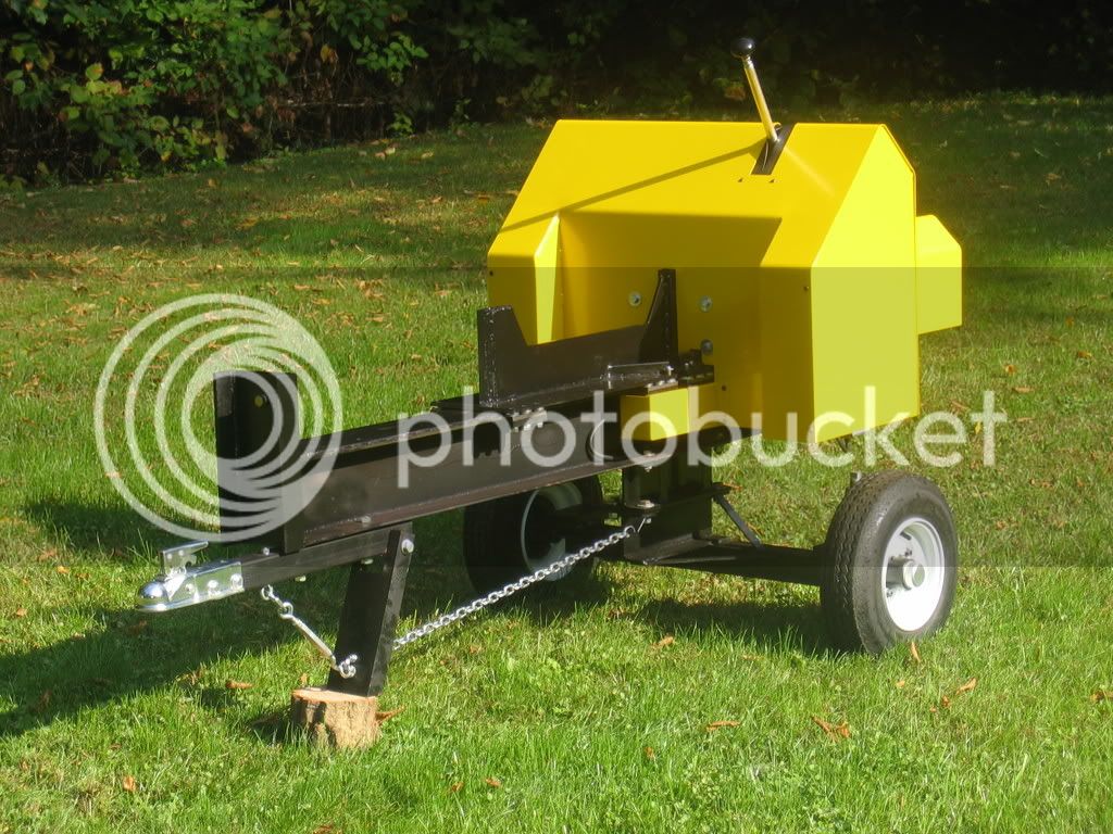
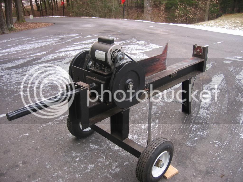
I just added it for any kind of comparison or even frame design ideas or whatnot.
Sent from my Galaxy Nexus using Tapatalk 2
Sent from my Galaxy Nexus using Tapatalk 2
bower4311
ArboristSite Operative
My apologies this is your thread,
when I get time I'll do some photos of the current state of my kinetic splitter
ps:Sorry for bad English
Good stuff can't wait
Sent from my Galaxy Nexus using Tapatalk 2
Similar threads
- Replies
- 33
- Views
- 4K
- Replies
- 4
- Views
- 469
- Replies
- 93
- Views
- 4K
- Replies
- 17
- Views
- 2K
Latest posts
-

-
-
 Removing a branch from a liquid amber/sweet gum - stability issues?
- Latest: singinwoodwackr
-
Anyone with a Harbor Freight Chain sharpener try and do a square grind?
- Latest: singinwoodwackr
-

-