You are using an out of date browser. It may not display this or other websites correctly.
You should upgrade or use an alternative browser.
You should upgrade or use an alternative browser.
Catersplitter Build Thread
- Thread starter Kevin in Ohio
- Start date


Help Support Arborist Forum:
This site may earn a commission from merchant affiliate
links, including eBay, Amazon, and others.
Those are some serious MAN skills you are sporting Kevin.
Question:
Are you planning to use the Hydrostatic Drive from the mower to make it "Self Propelled?"
David
I weighs 2 ton and we just use a truck or tractor. Wasn't worth the extra cost and time for me to consider it. This suits our needs and trust me, I've was planning and thinking through options for years.
")
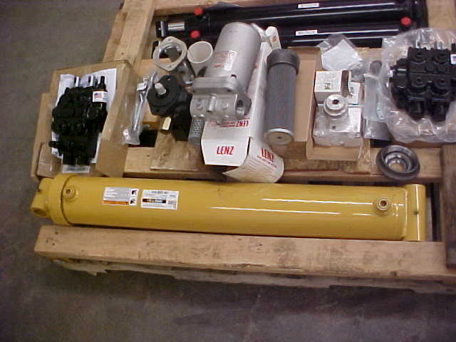
Got all the filters, strainers, 2 spool valve, auto cycle valve, coupler, pump bracket 28 gal pump, 2 3 1/2 x 24 cylinders for stabilizers, dump valve and 5 X 30 Prince Gladiator cylinder. All nice stuff.
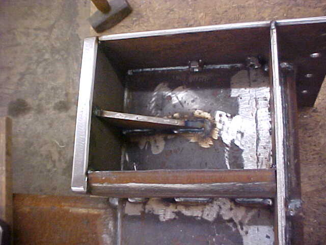
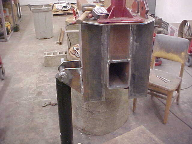
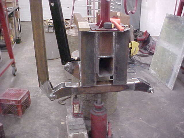
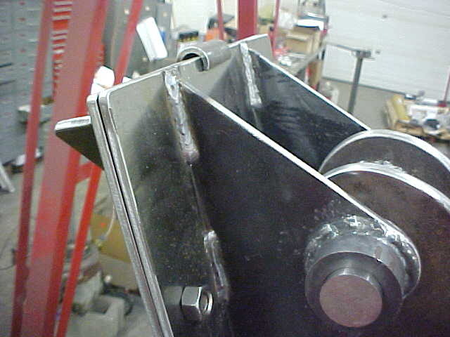
Camera makes it looked angled but trust me, everything is true and square. Put in a 3/8" angle brace behind the backstop and a leftover piece of the 1/2" box on the bottom edge.
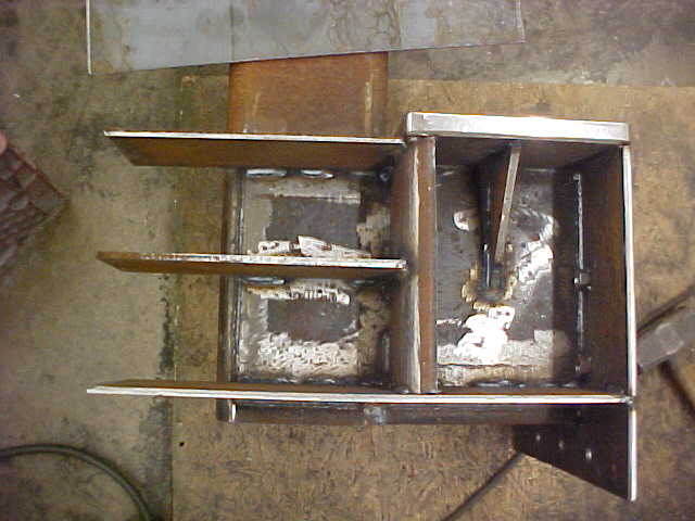
Using 1/4" plate for the outer edges and center brace. The "box" will serve as a mounting point for the stabilizer arms and the hinge for the swing away tables. Upper Cylinder mount will be on the lower back half of the box.
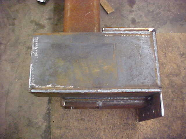
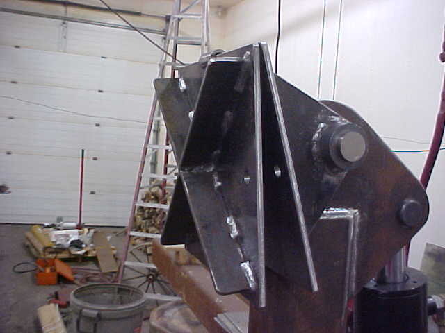
Enclosed everything with a piece of 1/4" plate and finished welding it up. I'll do the same on the other side
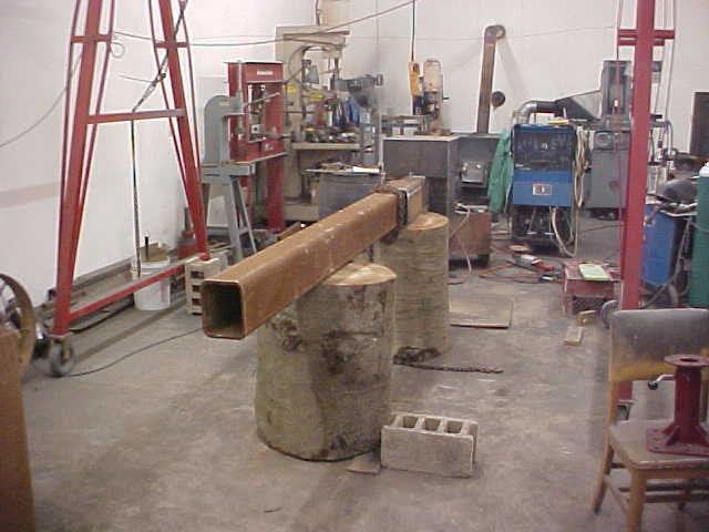
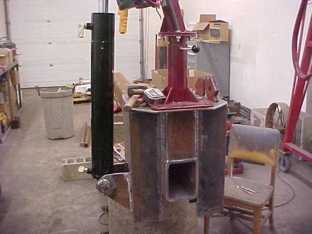
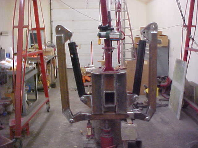
Got the other side all done and was ready to move on to the next phase. Decided it was time to get the top of the beam to the final height so I cut 2 28" diameter beech logs 32 inches long. With the 8 inch beam that makes it to the 40" height I want. This will be REAL nice for me to work at this height.
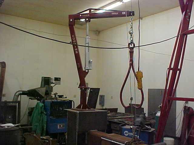
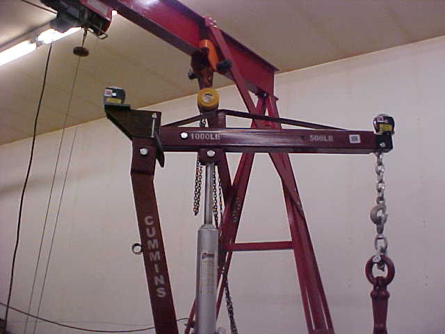
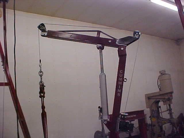
Had to play a little so I mounted the boom lift. This is going to make life a lot nicer. Caution as always when lifting stuff will be needed but as smooth as it moves you'll be able to move with one finger.
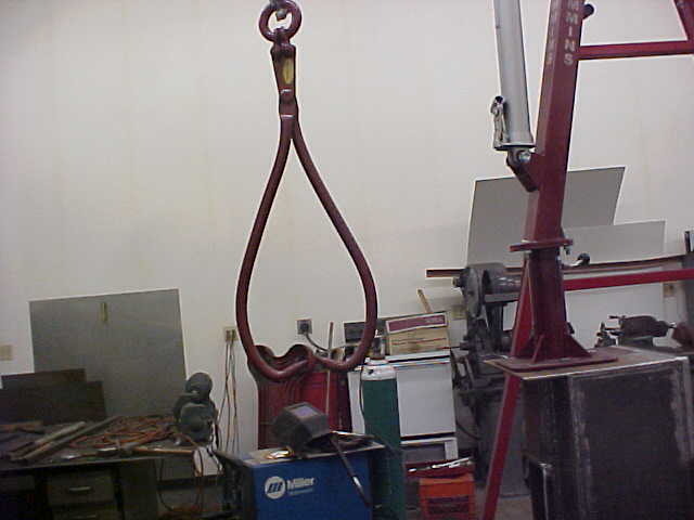
Best part about wedge on cylinder is you can split off the side of a big one and the boom holds it for you. With the swing tables you can move the big hunk out of the way and do the other side and repeat till you have a manageable size. That's the plan anyway! I'll put the cable on the tong later, this is just to give you an idea of what I'm doing. This also shows how you can back down the log or drag the chunks to you to split.
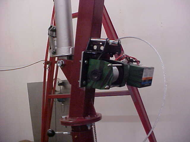
Started mounting up cordless Winching system. Had to mount the winch low enough to be able to work the quick release for unspooling. Figured up the best location and cut out a mounting plate, tacked it on to double check and it looks fine. Power leads look a little light to me but time will tell.
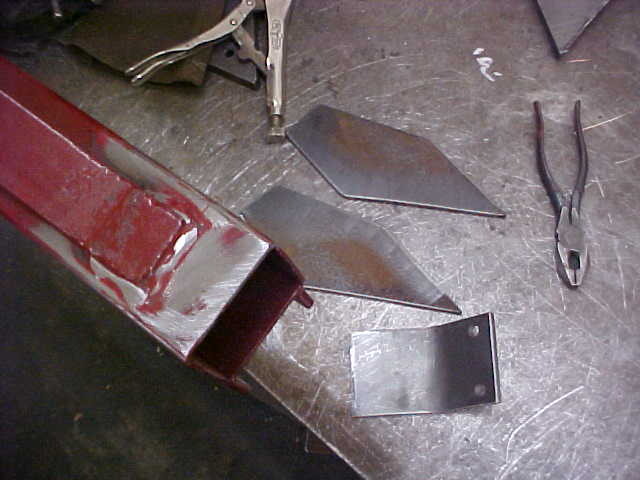
On the top I have to use pulleys for the cable guides. Took some measurements for cable clearence and cut out some steel for the rear bracket. I'll trim more off the front side of those brackets as it isn't needed. Winch "says" it will pull 3000 lbs. Pulleys are rated for 2000lbs and using 3/16's cable. Shouldn't overload it!
Trimmed off the excess on the rear pulley mount and made up piece to bolt the pulley to. Bent it so it will tie into the beam as well when welded.
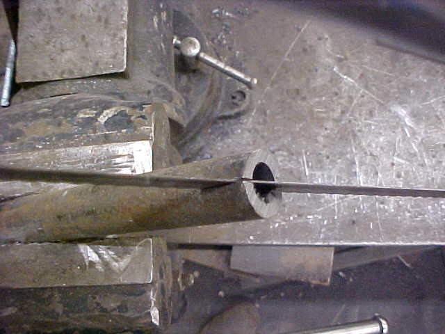
The pulleys were open faced. Meaning, it would be possible for the cable to slip off so I needed some keepers. An easy way to do that is to saw down the middle of the appropriate size black pipe. Then cut it off and you now have 2 keepers. I deburr them real nice prior top welding on.
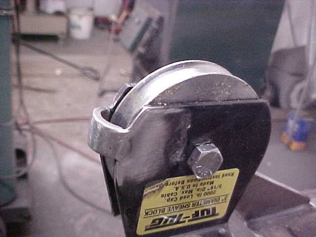
Welded on and smoothed up. That will keep it where it belongs. I'll do the same to the front pulley.
Cable clearances all look good and here it is all done. Once it's all painted up it should look pretty good.
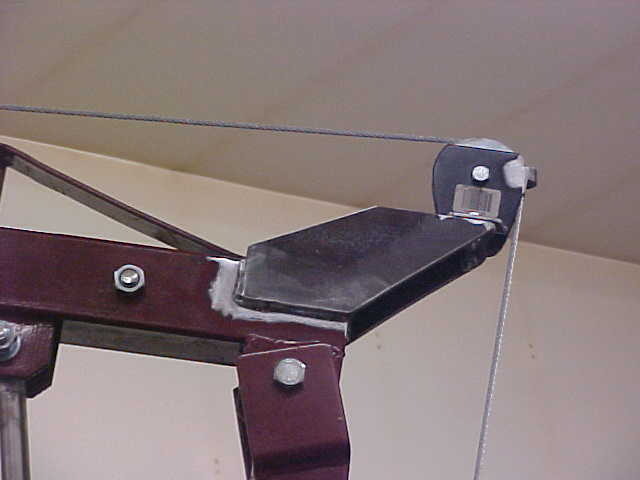
Center mounting plate/gusset runs basically down the center of the 2 side brackets.
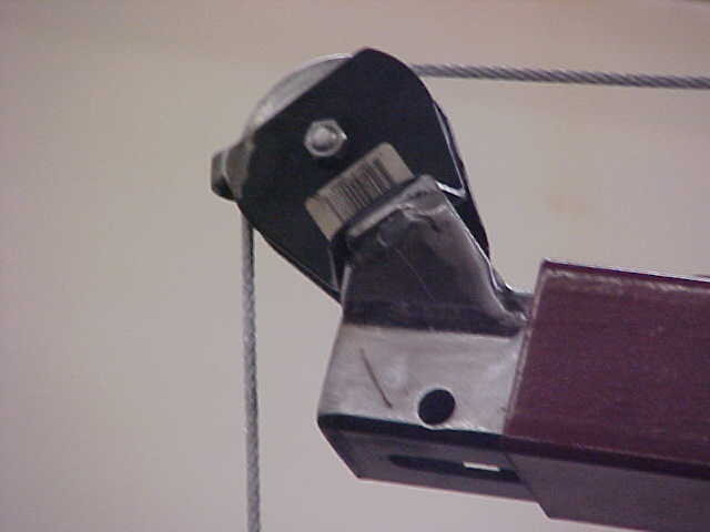
End pulley mount is a small piece of heavy angle iron. 45 degree mount allows more front clearance on the cable. Made filler pieces to tie into the box beam from the open ends of the angle iron. Welded the nuts on the inside for the pullet bracket'
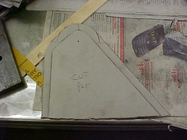
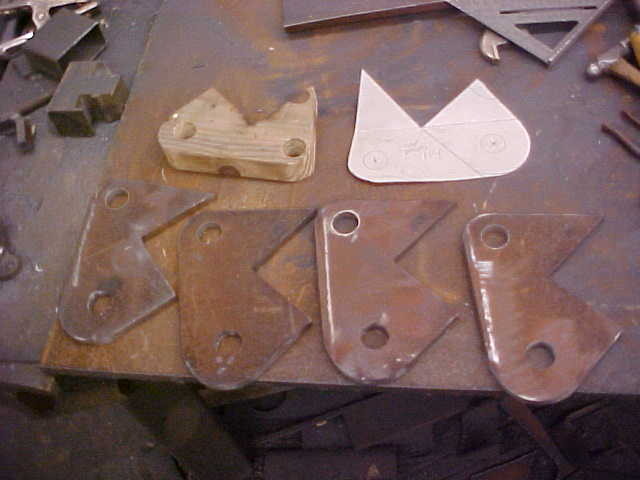
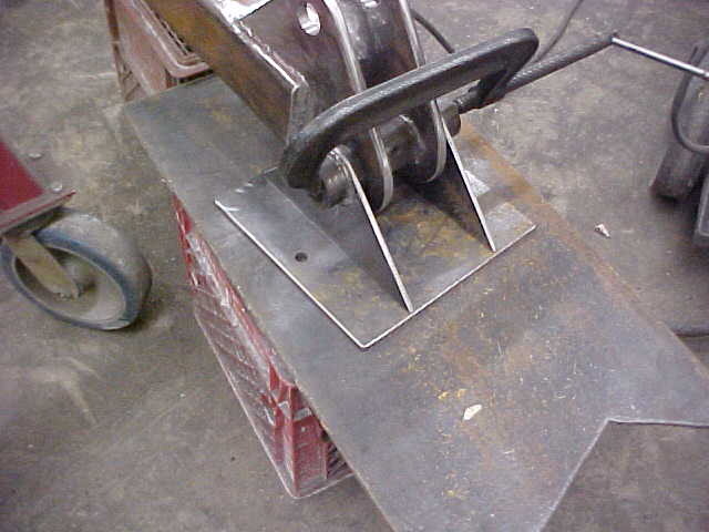
Next phase is setting up the stabilizer arms. did my measurements and drew up a bracket pattern for the cylinder mount. After finalizing the design I made another pattern a 1/2 inch smaller for a cut pattern I'll transfer to a piece of wood. Notice I marked the hole center. I'll draw the pattern on the steel and drill the holes first.
redheadwoodshed
Freebird
That auto cycle valve would be a nice addition.I was thinking about adding one to my speeco.
Rattler05.5
ArboristSite Member
Why wait?
Not the first to be fooled by this. Kevin is doing us a favor and showing us the process that he went through to build this splitter. This thread is all what it took to build this ⬇
Here is the final product,
http://www.arboristsite.com/firewood-heating-wood-burning-equipment/205803.htm
Nice Work. I'm looking forward to seeing the end product!
Not the first to be fooled by this. Kevin is doing us a favor and showing us the process that he went through to build this splitter. This thread is all what it took to build this ⬇
Here is the final product,
http://www.arboristsite.com/firewood-heating-wood-burning-equipment/205803.htm
cowroy
Addicted to ArboristSite
opcorn:Arbonaut
Go Climb It
Lookin' good.
If you like this thread, I'd appreciate you guys rating it. This takes a little more time to do than I thought but wanted to do it if it'll help others.
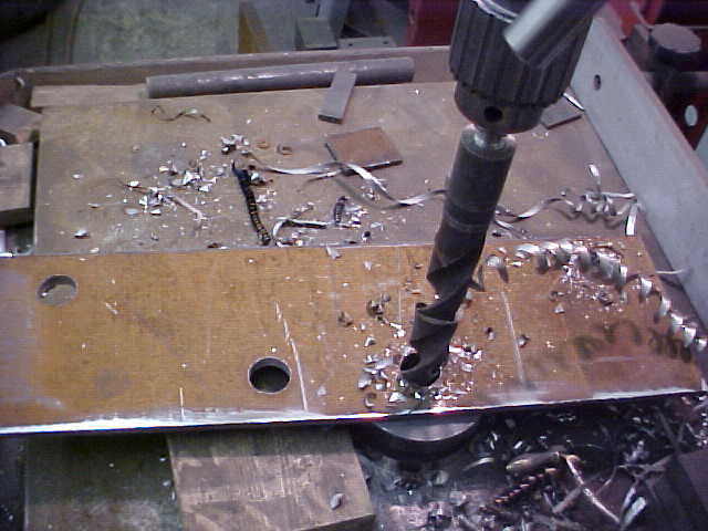
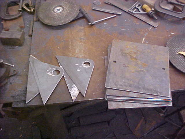
I drill a small pilot hole then step up in size to .4375. I then used the final size drill, 1.250. in the .375 plate.
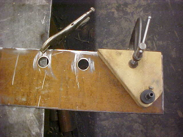
Once the holes are done I use them as a locator. I dropped a hole saw in through the wood pattern and clamped it all together with a C clamp. Dead simple way of doing it and keeps everything in place. saves a lot of excess trimming this way.
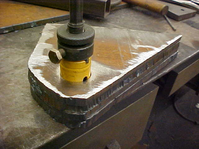
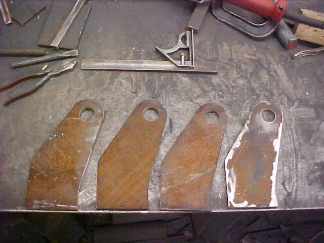
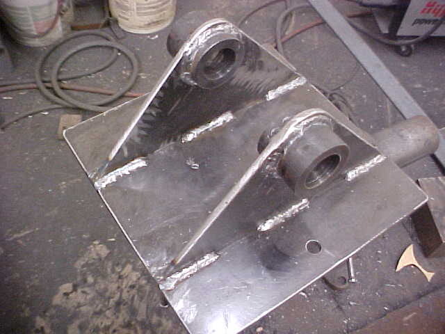
Here's all 4 of them straight from the hand held plasma cutter. I've leave the hole saw in all four and grind them all at once. easy to keep everything square and exactly the same. Makes welding set up nice and measurements will repeat to the other side.
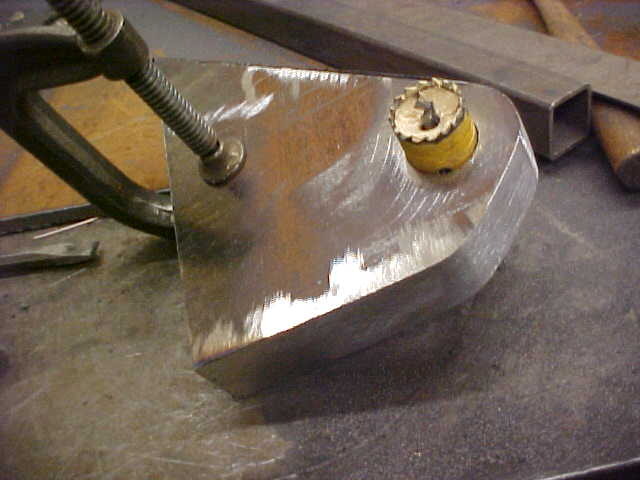
Used a 9 inch angle grinder and you can see how nice it makes it. Used a belt sander on the corners. I use a square to assure the edges are 90 degrees.
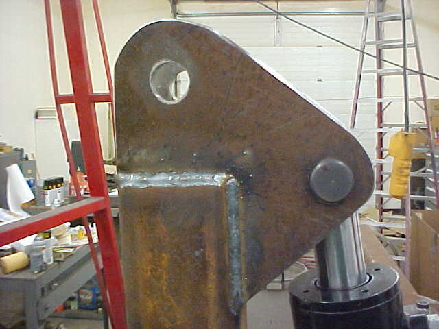
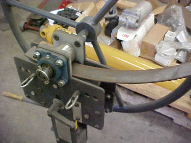
Tacked on one mount, checked for straightness and put the cylinder on with the other mounting plate. I then tacked it on as well.
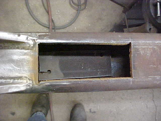
I made it so the port can go on either side. I'd like to keep it on the bottom if possible to protect it from the logs. Hoses will come out the inside of the box beam. Cylinder won't be straight up but the arms hopefully will.
Scrap yard didn't have any double or triple wall pipe so I drilled some 2" bar stock for collars. Made them about 1 inch long and welded them on. This takes the stress of the pins and mounts.
For the arms themselves I need some clearance so I'll cut away some of the box once I get the little brackets welded on and drilled. I'll use a modified hole saw to do the holes once they are in final position like this.
I drill a small pilot hole then step up in size to .4375. I then used the final size drill, 1.250. in the .375 plate.
Once the holes are done I use them as a locator. I dropped a hole saw in through the wood pattern and clamped it all together with a C clamp. Dead simple way of doing it and keeps everything in place. saves a lot of excess trimming this way.
Here's all 4 of them straight from the hand held plasma cutter. I've leave the hole saw in all four and grind them all at once. easy to keep everything square and exactly the same. Makes welding set up nice and measurements will repeat to the other side.
Used a 9 inch angle grinder and you can see how nice it makes it. Used a belt sander on the corners. I use a square to assure the edges are 90 degrees.
Tacked on one mount, checked for straightness and put the cylinder on with the other mounting plate. I then tacked it on as well.
I made it so the port can go on either side. I'd like to keep it on the bottom if possible to protect it from the logs. Hoses will come out the inside of the box beam. Cylinder won't be straight up but the arms hopefully will.
Scrap yard didn't have any double or triple wall pipe so I drilled some 2" bar stock for collars. Made them about 1 inch long and welded them on. This takes the stress of the pins and mounts.
For the arms themselves I need some clearance so I'll cut away some of the box once I get the little brackets welded on and drilled. I'll use a modified hole saw to do the holes once they are in final position like this.
Last edited:
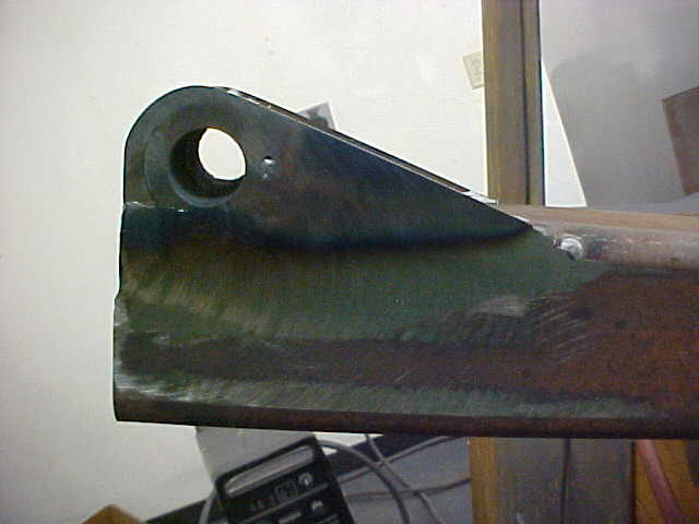
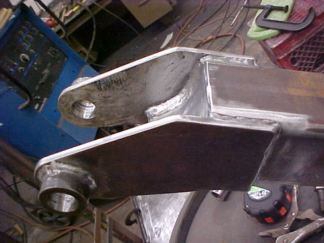
Here it is welded and drilled. Next is to cut away for clearance.
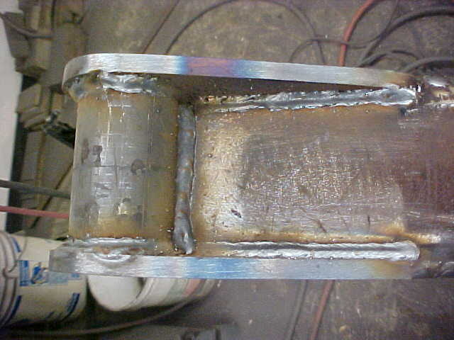
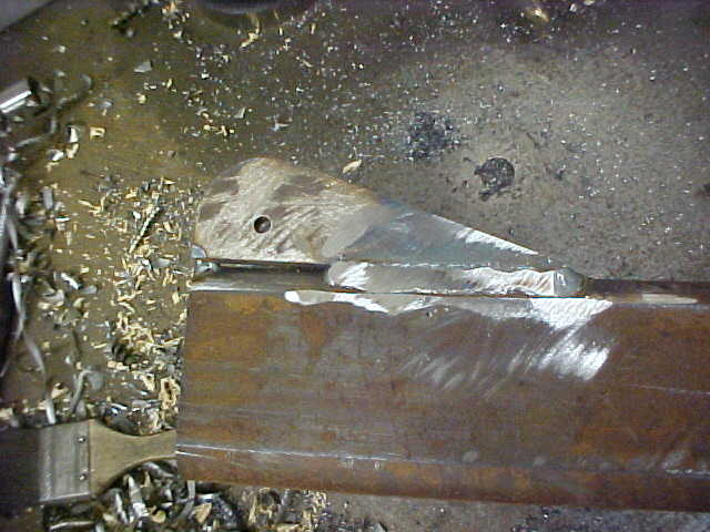
Same 2 inch rod gun drilled for 1 1/4" pins. Flattened the bottoms as the pin sits almost to the box beams edge. All welded up on the bottom side now. drilled and tapped for a grease zerk on the non showing side.
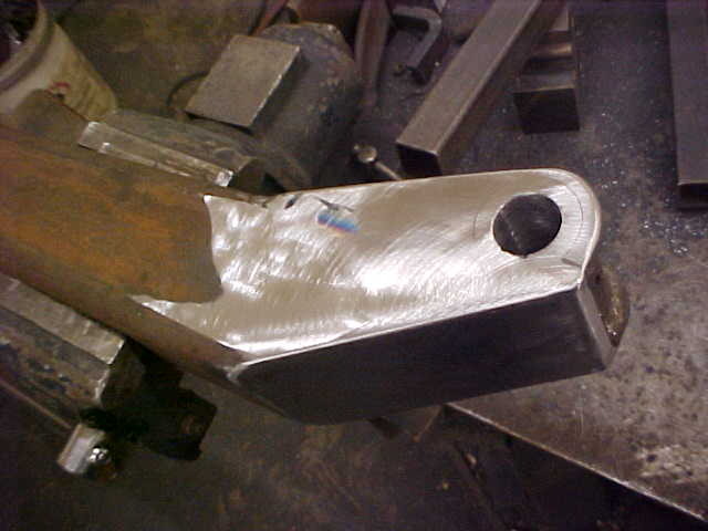
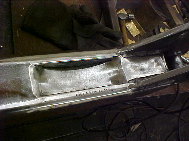
Cut out the needed amount for arm clearance when folded up. I then inlaid a plate into the opening and welded it in. Ground everything smooth and here is the finished arm end that is pinned to the lower splitter mount.
Drew up a pattern for the lower arm mount and cut them out the same way as before.
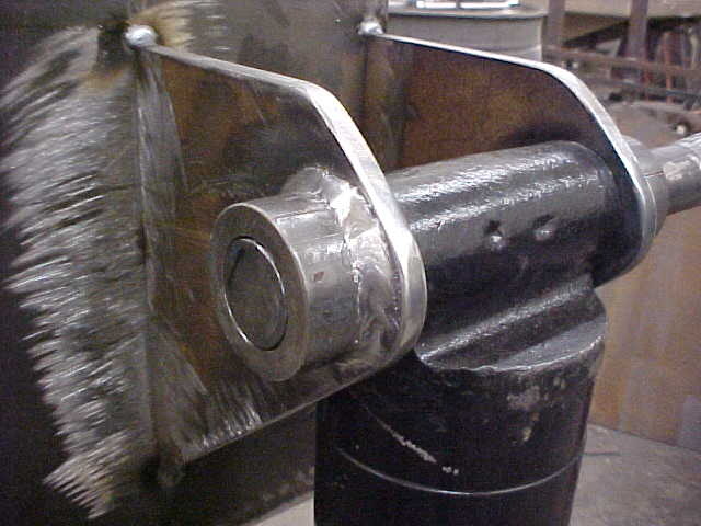
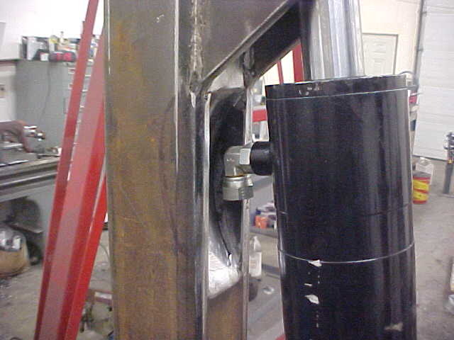
Welded the plates on and inlaid a section of large pipe on the inside. This is another area I needed clearance in as this is what the stabilizer arm swings up/into. I just did one side so I can fine tune the measurements in case I mis figured something. Once it is checked and okay, I'll do the other side using the same measurements.
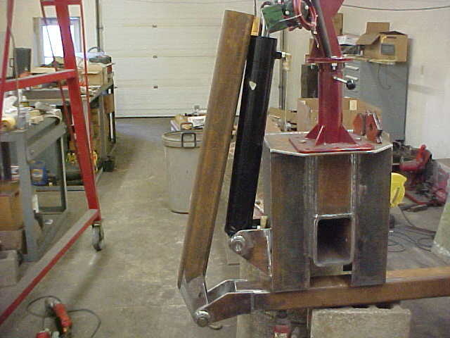
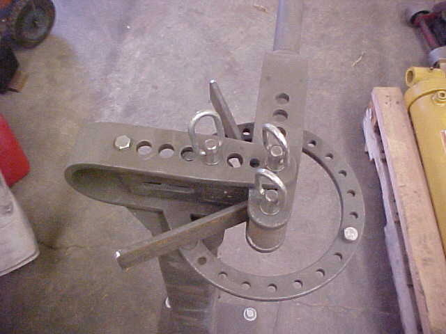
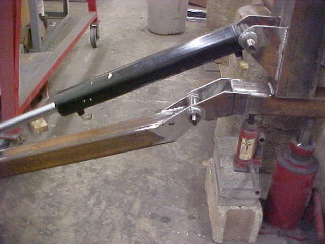
Slid the lower mount underneath and held it up with some jacks. Installed the arm to check the swing. The arm will be straight when cylinder is fully closed. Doesn't look like I'll be able to have lines underneath as it looks too close.
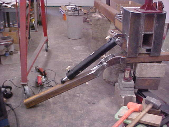
Down looks pretty good and gives it around a 10 foot width with pads. Ram's eye centerline will be flush with end of box beam. Lots of stuff to think/worry about here.
Drew up another pattern for the cylinder ram mount/foot mount. Used 1/2" plate this time.
owbguy
ArboristSite Operative
excellent thread. excellent skills on display.
how long did it take to get this far? how long was the total build?
I'll I can say is
how long did it take to get this far? how long was the total build?
I'll I can say is
excellent thread. excellent skills on display.
how long did it take to get this far? how long was the total build?
I'll I can say is
Started on it at the end of January and 3 1/2 months later it was done. Work loads of overtime(7 days with some 10's) so I got about 4 hours work time when nothing was up. To this point was about 3 weeks.
Thanks for the kind words and glad you guys are getting something out of it.
Last edited:
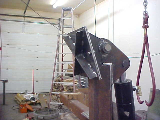
Tacked it on first and checked for any problems. Everything checked out okay so I welded them on for keeps.
Cut the bottom box beam and welded the lower mount on the other side. Brought out the Papa bear Jack and his little cub to hold it in place for any adjusting. Once centered and everything was okay I welded it on.
With the bottom mount set I went from that to set the upper brackets position. Tacked it on good enough to hold. I'll start on the ground contact pads for the arms next.
Cut out 6 10" X 10" plates that are 1/2" thick and drilled holes in them all. Made a pattern for the mounts and cut out 4 of those. I'm making 2 sets of bolt feet. One will have thick rubber if I work on concrete or surface I don't want to chew up and the other set will have the normal steel shoe.
Put a thin washer on one side of the pin and clamped it in place. Simply laid the arm down on a flat surface and welded it up.
On these I needed it a little wider on the inside to clear the box beam so I made up 1/2" collars. I used the same 1" collars on the outside and finish welded everything. Plate sucked in a little but the press put it right back and pin slides through freely.
For the steel shoe I got some 1/4" X 1 1/2 strap and bent them up. I'll make up 3 more and have an X on the bottom of the shoe.
Got the X welded up and bolted it on. The feet can pivot about 135 degrees if you want them out of the way when the arms are up.
Last edited:
ss~zoso~ss
ArboristSite Operative
you NEED to post a video of this beast in action!
jags
ArboristSite Guru
Awesome build. I am eating it up. Keep it coming.
Took a short piece of pipe and opened it up. Welded it on to the shoe side once it was bolted tight. This is so I can throw it up on the arm while in the air and not have to wrestle to get the bolts in.
Here is how it works, built in third hand. Don't know how much I'll trade to the rubber pads but it will be easy. I'll make the rubber padded ones later when I find some thick 2 inch + rubber for them.
With the stabilizers done I started looking at figuring out the 2 tables layout. It became apparent with the hydraulic ports up it was going to be close. I wasn't happy with the idea anyway so I decided to make a pocket for clearance in the arm. This way I'd protect the lines and make it easier for the tables. Marked the offending area and cut it out. Notice the drilled hole it the cut waste laying in the bottom. I do this to save the plasma tips so the splash back doesn't occur on start up.
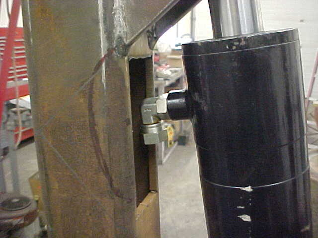
Put the arm back on to double check and it looked good. With the inlay I'm planning it shouldn't hurt the strength any.
Got some 2" strap and bent it in the ring roller. It'll give a finished look to the pocket.
Took 2 pieces of 1/4" flat strap and welded it on the backside to of the curve. Beveled all the edges hard and tacked it in. Then ground it all flush and smoothed it.
Fully closed here and there is now plenty of room. little bit of work but I'm sure it'll save a line break in the future.
Full down looks more like what I had planned from the start as well.
Last edited:
Steve NW WI
Unwanted Riff Raff.
If you like this thread, I'd appreciate you guys rating it. This takes a little more time to do than I thought but wanted to do it if it'll help others.
Done. I gave it 3 stars. After all, the wedge is on the wrong end! :hmm3grin2orange::hmm3grin2orange: Seriously, I'd have given it 10 stars if they'd let me.
On the pads, why make another set to bolt on? Take your pads that are cut for the rubber, weld on some bar stock to match the x pattern: in other words, when they're in use, the bar stock will sit on either side of your X bars and hold it in place, just set the bottom pads down and put the outriggers down on em. I could draw a sketch if you don't follow my description. For rubber, if you can find a small dairy that's not milking any more, see if they have any rubber cow mats you can scrounge. 1/2 to 1" thick depending, and plenty durable.
Wish I had half the fab tools you have. At least I work in a shop that can make anything (we build our own punch press tooling), but no employee discount on stuff I get made. Little things can sometimes be done on break for free though. Our new 6000W laser cuts 1" steel really nice...
Similar threads
- Replies
- 19
- Views
- 2K
- Replies
- 17
- Views
- 2K
- Replies
- 3
- Views
- 1K
- Replies
- 43
- Views
- 2K
- Replies
- 11
- Views
- 2K
Latest posts
-
 Will pulling the starter(slowly) without gas in the tank cause engine scoring?
- Latest: Vintage Engine Repairs
-
-

-

-

-

-
