Blazin
Addicted to ArboristSite
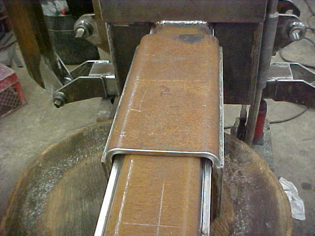
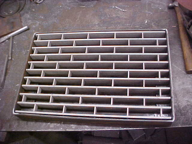
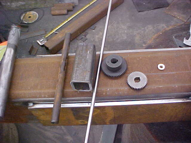
Awesome work as usual Kevin!  That ring roller is a nice tool, beats using a piece of well casing for bending like I do
That ring roller is a nice tool, beats using a piece of well casing for bending like I do 


 That ring roller is a nice tool, beats using a piece of well casing for bending like I do
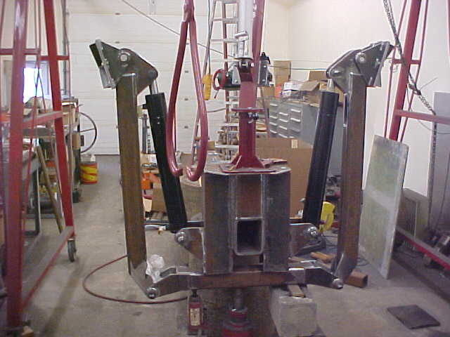
Done. I gave it 3 stars. After all, the wedge is on the wrong end! :hmm3grin2orange::hmm3grin2orange: Seriously, I'd have given it 10 stars if they'd let me.
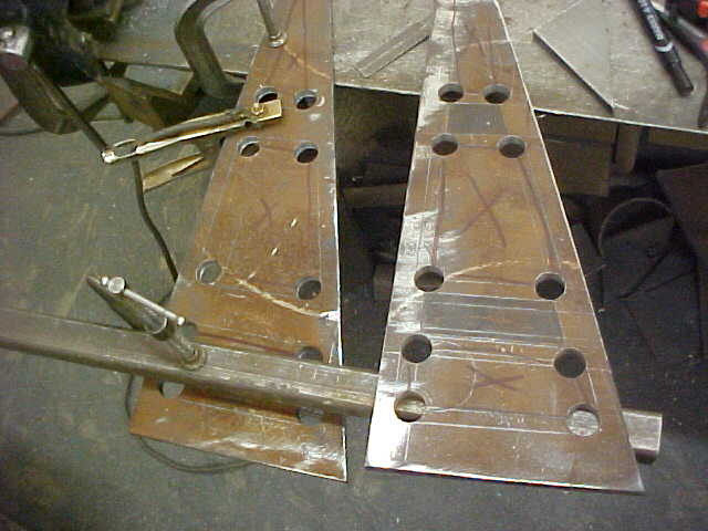
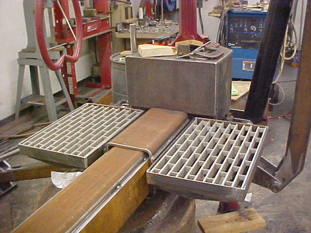
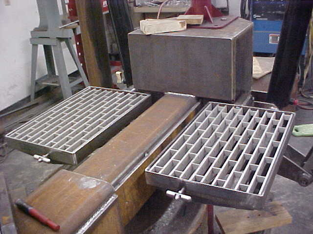
On the pads, why make another set to bolt on? Take your pads that are cut for the rubber, weld on some bar stock to match the x pattern: in other words, when they're in use, the bar stock will sit on either side of your X bars and hold it in place, just set the bottom pads down and put the outriggers down on em. I could draw a sketch if you don't follow my description. For rubber, if you can find a small dairy that's not milking any more, see if they have any rubber cow mats you can scrounge. 1/2 to 1" thick depending, and plenty durable.
Wish I had half the fab tools you have. At least I work in a shop that can make anything (we build our own punch press tooling), but no employee discount on stuff I get made. Little things can sometimes be done on break for free though. Our new 6000W laser cuts 1" steel really nice...
") As you said, we'll agree to disagree.
As you said, we'll agree to disagree.


Enter your email address to join: