redheadwoodshed
Freebird
What a beast that thing is.The toughest old wood ain't going to stand a chance!


Awesome build thread Kevin, I love to see a pile of steel turned into a vision!
What amp is that miller you have? Just curious because my lincoln 255 with .035 wire burns in nice up to 3/4", after that I usually have to preheat to get the penetration.
")
Haven't found anything yet. Problem with most newer tires is dealing with the steel belts. It's hard enough cutting thick rubber without steel in it, I can't imagine trying to do it with one that does. Something will turn up in time, there is no real rush on that one. We have gotten earthmover tires before and they were corded. It's just, what do you do with the rest of itKevin:
Did you ever find any rubber feet for it???
I had to drive around a mack truck blow-out tire this morning.
The tread would most likely work well. Stop and pick one up.
David
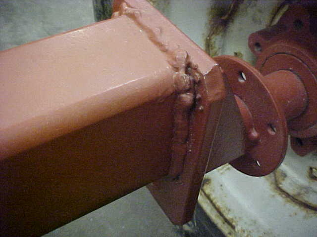
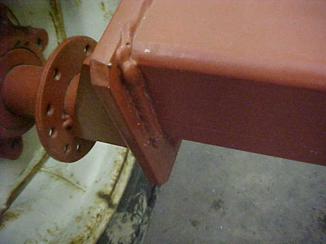
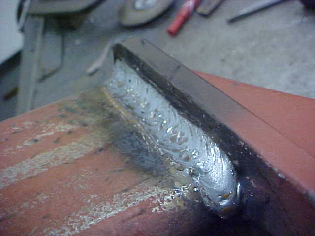
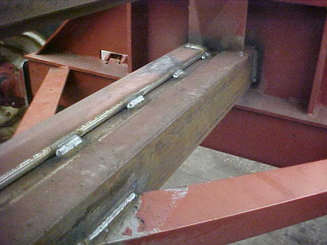
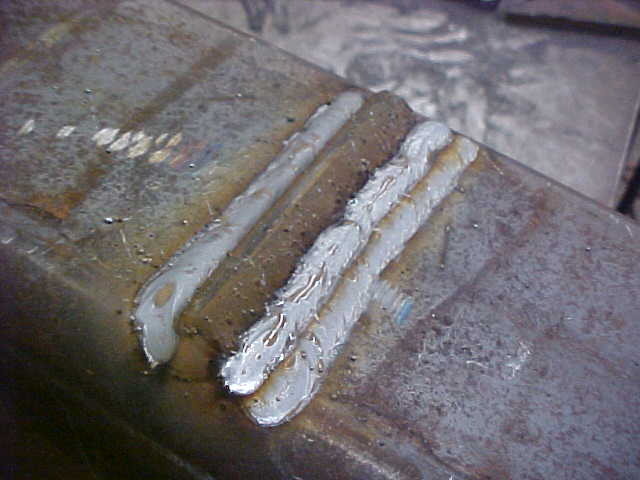
I've got a Miller 250X and a Miller Syncrowave 250, which is stick capable. As shown, I tend to V groove stuff that is really critical to me with several passes of weld. That said, it's pretty easy to blow through 1/2" plate when it's cranked up. Probably not right by the book but it has worked well for me over the years.
I started out stick welding everything as that's all we had at my former job. Lots of repairs done while I was there and learned a lot about what works and doesn't. Nothing like welding so much the stinger is too hot to hold even with welding gloves on
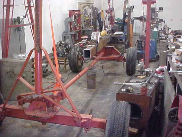
Thanks to all for the kind words and glad you guys are getting some from this. Projects like this are my recreation from the daily grind. Big plus is it makes your life easier and will last a long time.
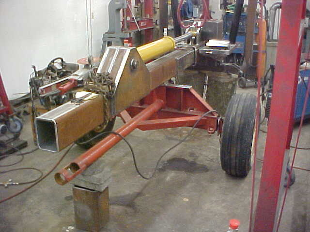
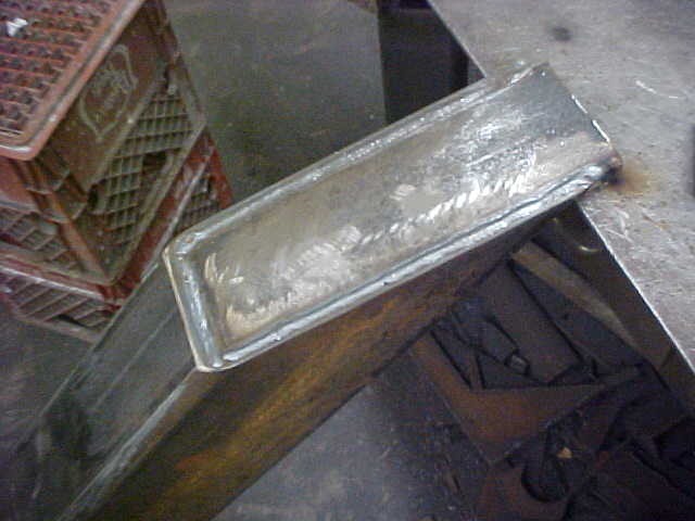
 and I know your build is already done). First the angle from the horizontal blade is too sharp. I donot believe that it will stand, although very thick(!), a long time. Second, at least I didn't see it, did you streghten the bolt hole for the cylinder on the wedge end like on the stationary end? I think it would be a good idea. Third looking at the probable power of your splitter, I believe that you are wasting a lot of potential energy not going directly to a eight cut blade. That will just zip through normal wood and you would be much quicker with a higher cut amount with one passing. I hope that that was clear .
Hello Kevin,
Going great! Three things I do not approve (if I may say so
Of course we all have understood by now that you donot own a chainsaw and expect to cut all your wood with the splitter!
7
edit: one thing I forgot to mention, for that build sofar you sure must have eaten a lot of corn flakes! :hmm3grin2orange:
Awesome job! I wish I had the talent you have.
This is by far the most complete build that I have seen yet!!! Great job and good on you to take Pics along the way!!
Enter your email address to join: