Catersplitter Build Thread

Arborist Forum

Help Support Arborist Forum:

This site may earn a commission from merchant affiliate links, including eBay, Amazon, and others.
MVC-021S_25.JPG


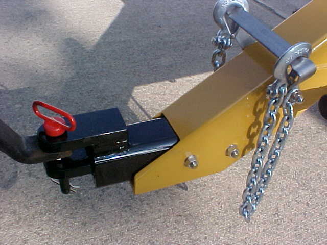
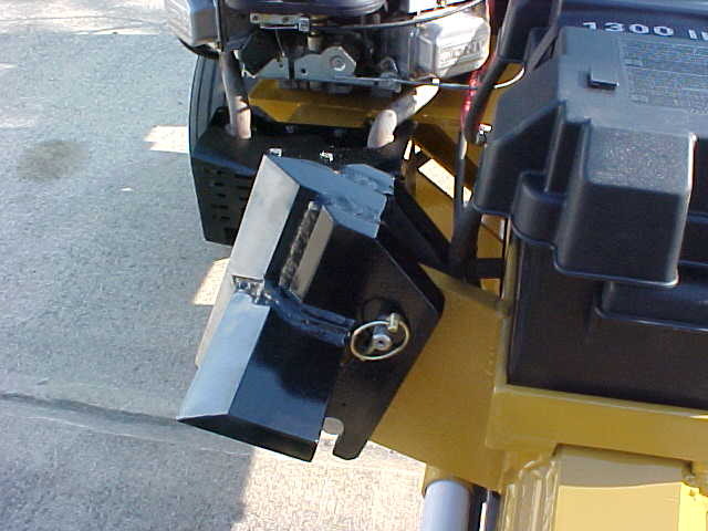
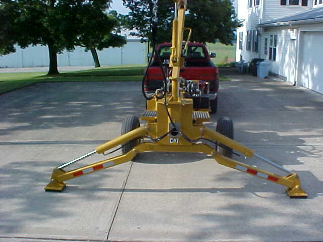
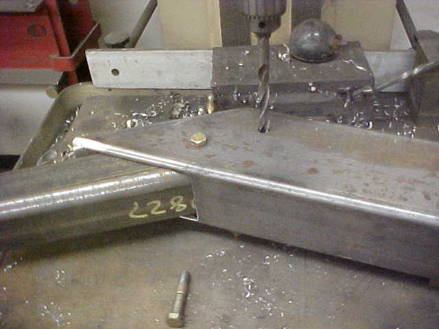
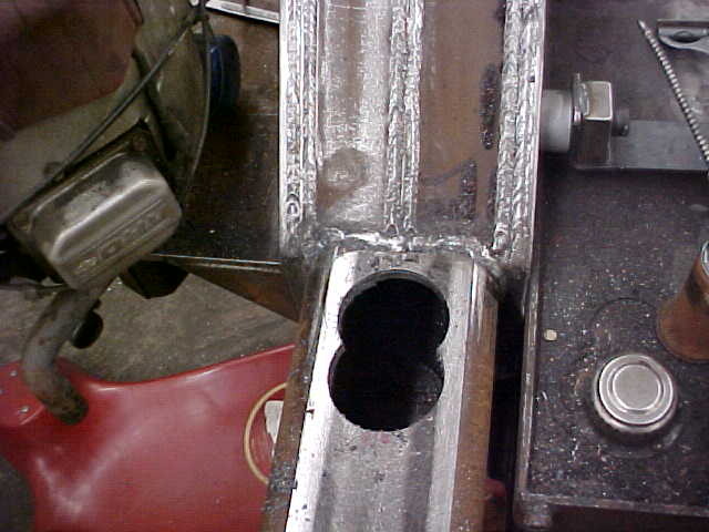
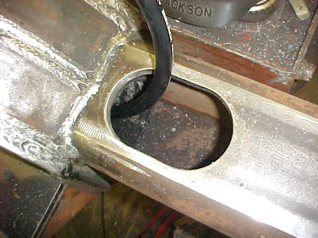
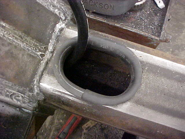
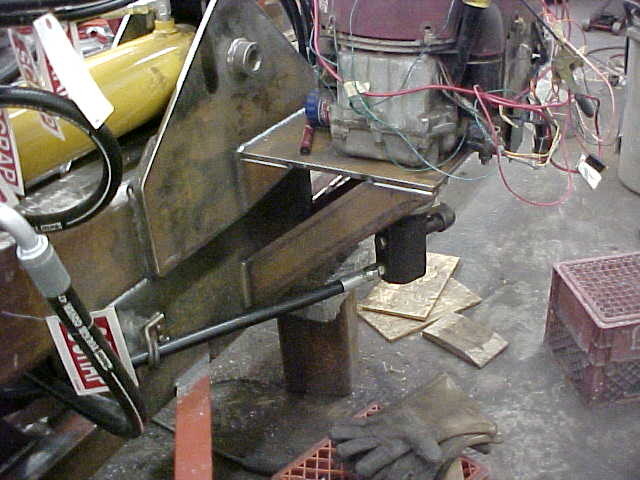
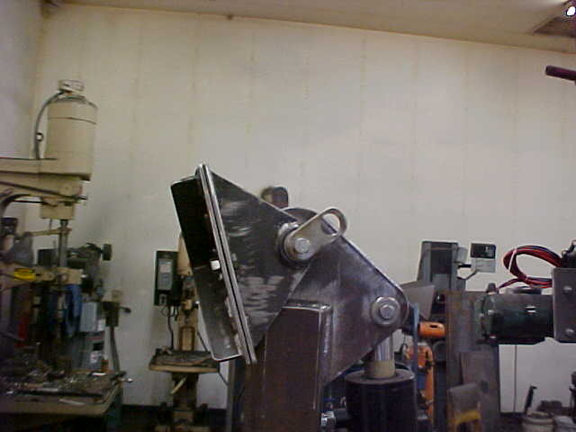
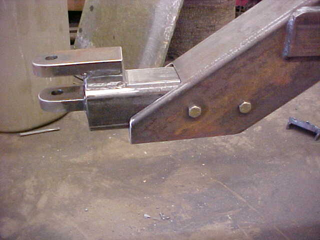
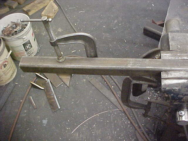
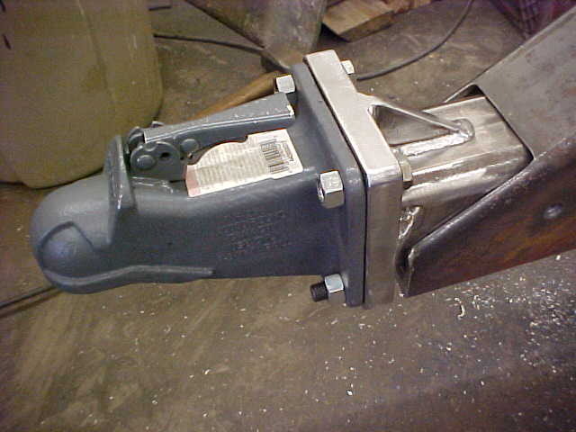
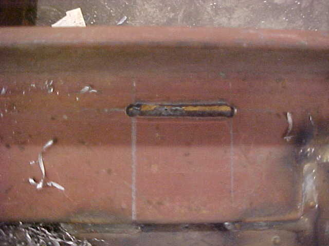
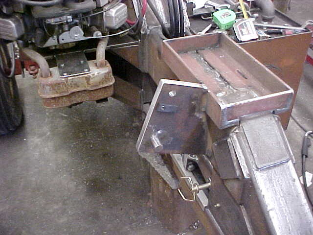
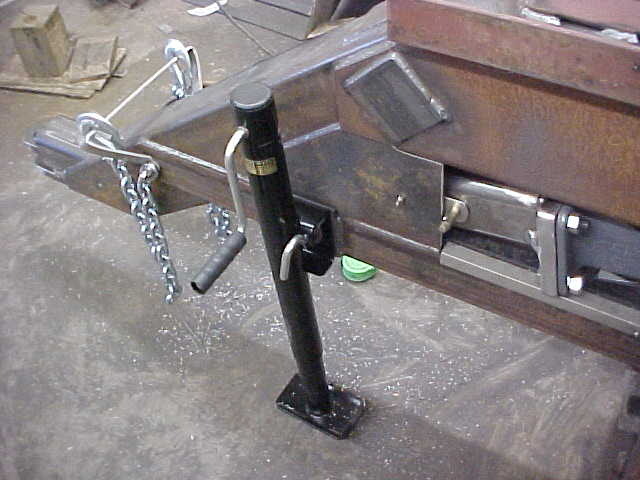
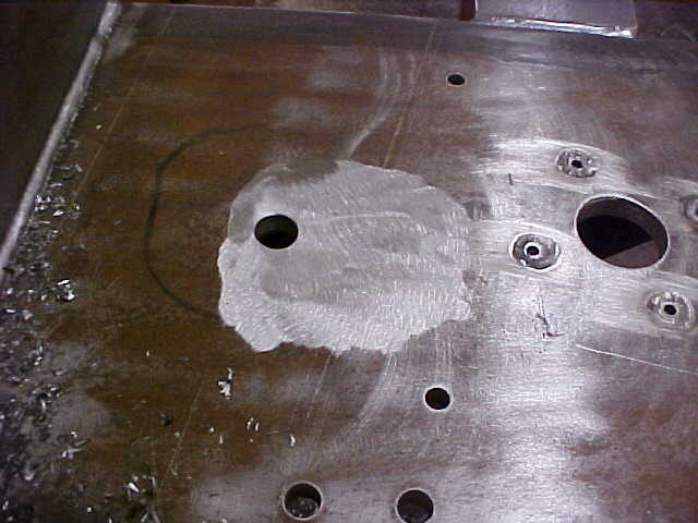
After a lot of measuring I drilled the holes for the hitch receiver. I want to be able to flip the hitch over so the splitter will remain level when using a truck or a tractor. I'll make the hitch a drop for the tractor, turn it 180 degrees and it's a riser. Doing this on the drill press bed keeps everything straight.

MVC-018S_46.JPG


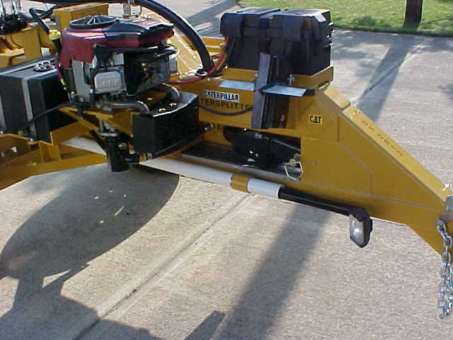
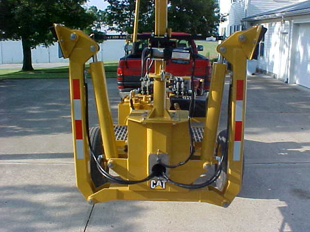
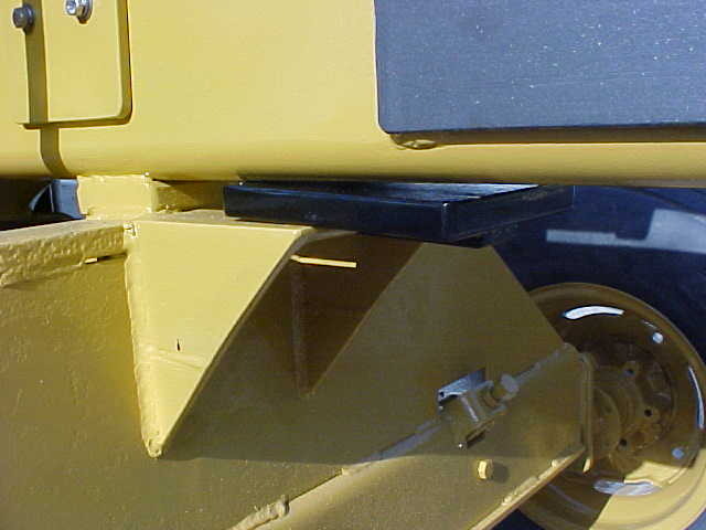
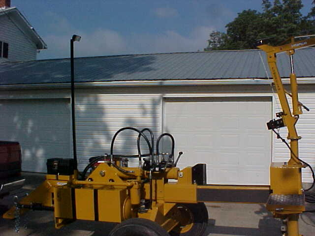
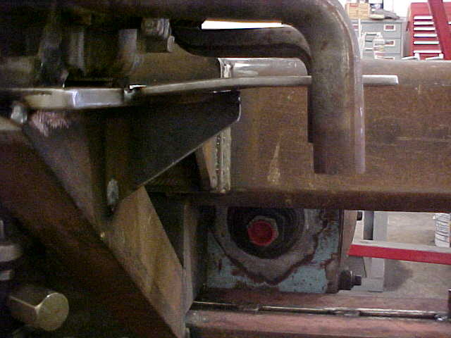
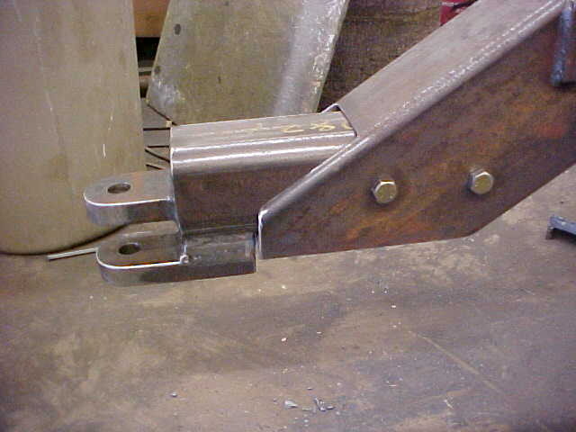
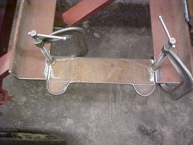
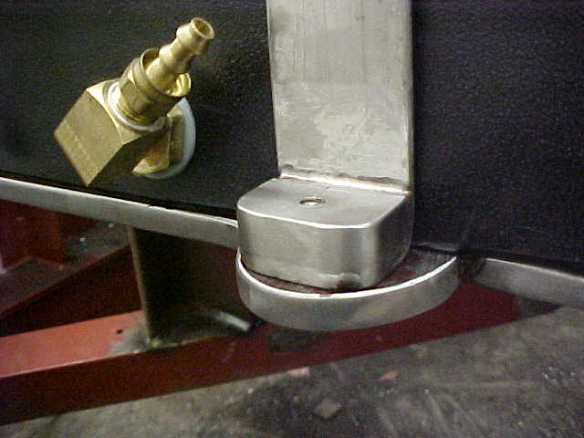
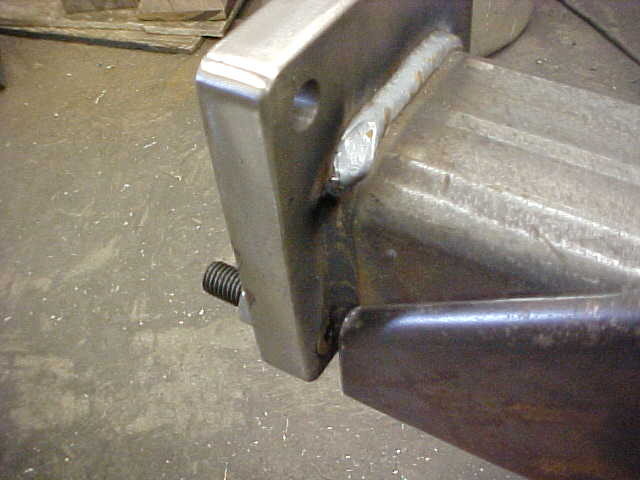
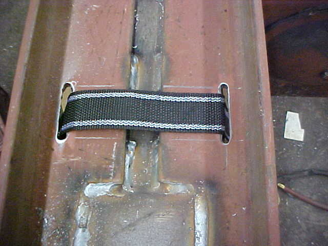
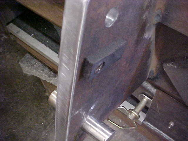
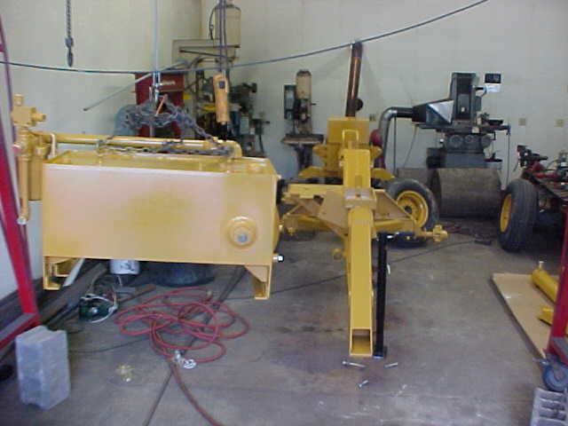
I put it in place and made sure everything was even and put a few tacks on. Check again and start final welding it.

MVC-019S_45.JPG


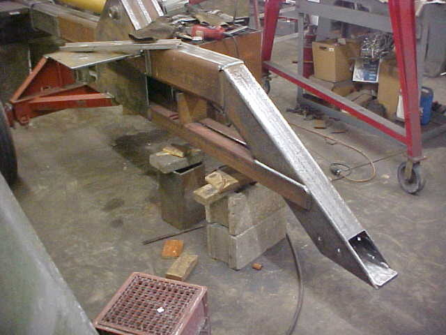
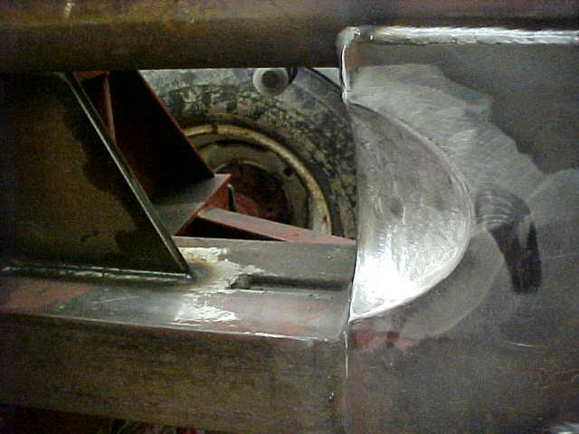
Everything ties together making it a lot stronger. Looks a lot better better now as it comes together. You think of things in your head but you're never completely sure till you see it in real life.

MVC-020S_35.JPG


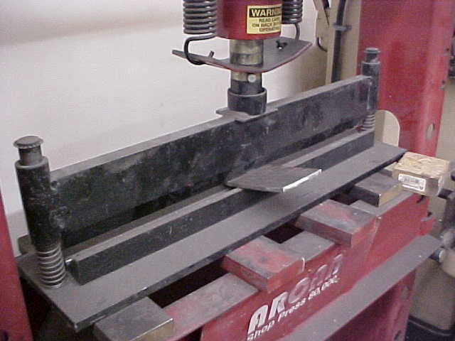
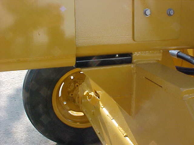
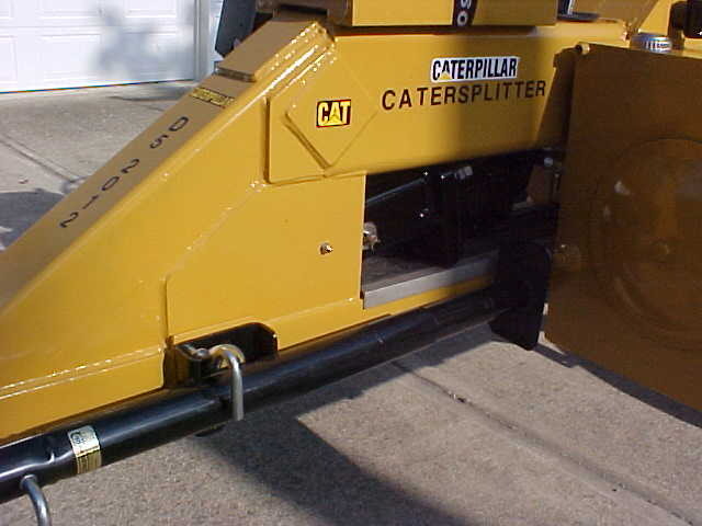
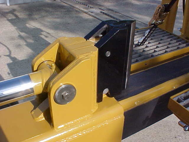
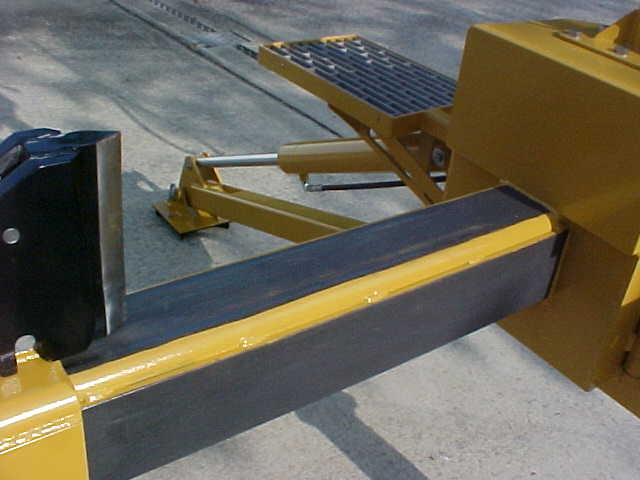
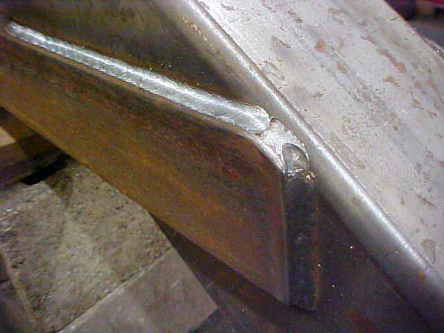
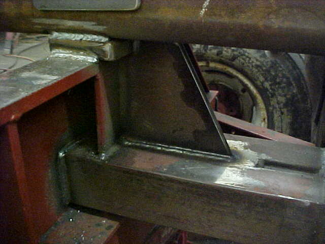
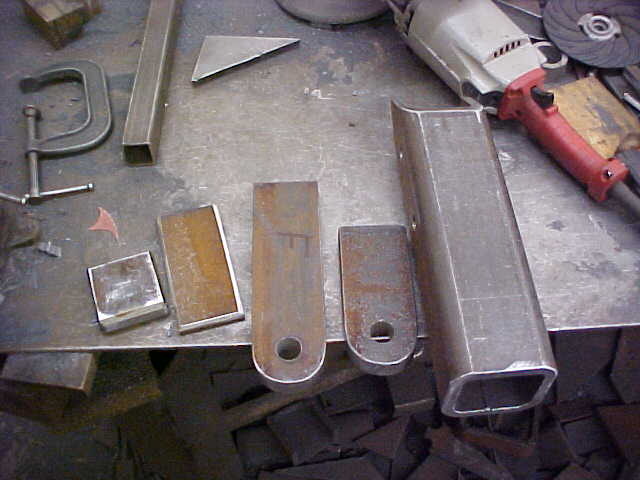
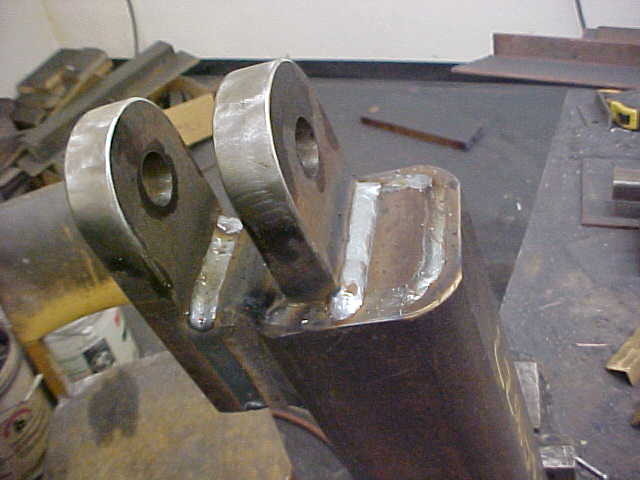
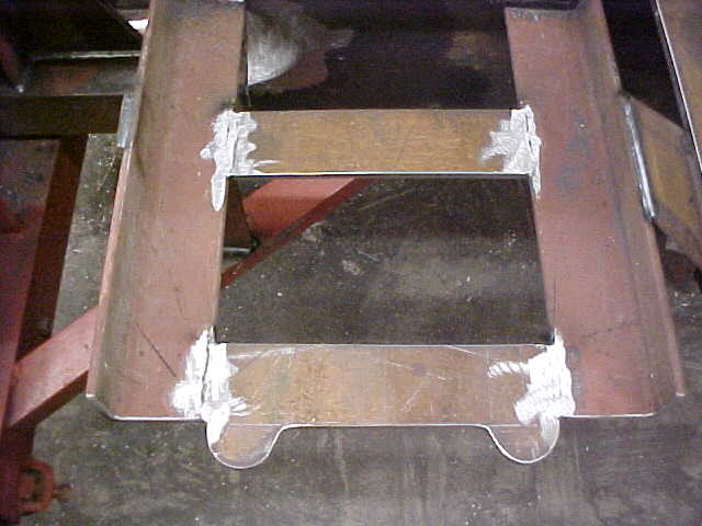
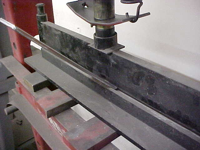
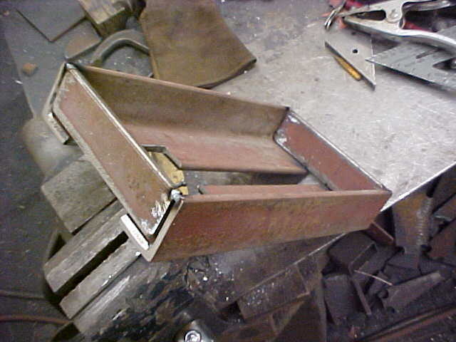
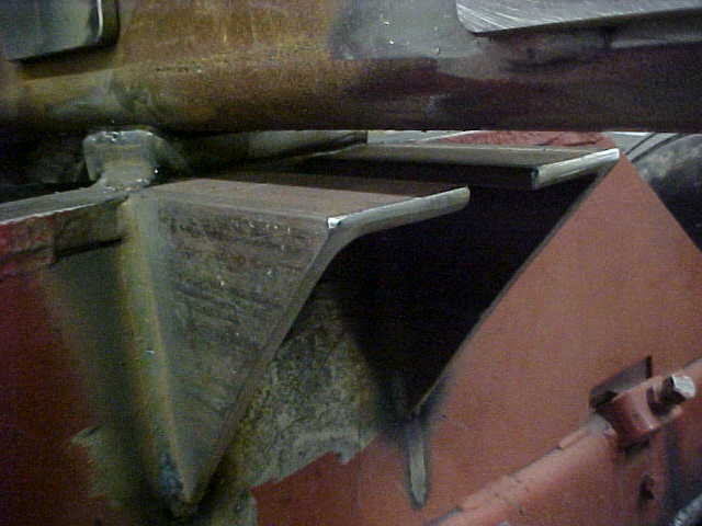
Wanted to put some gussets where the 2 big boxes meet. Cut out some .375 plate and bent it in the press to match the splitter.

MVC-021S_26.JPG


One down and a few more to go!

MVC-018S_47.JPG


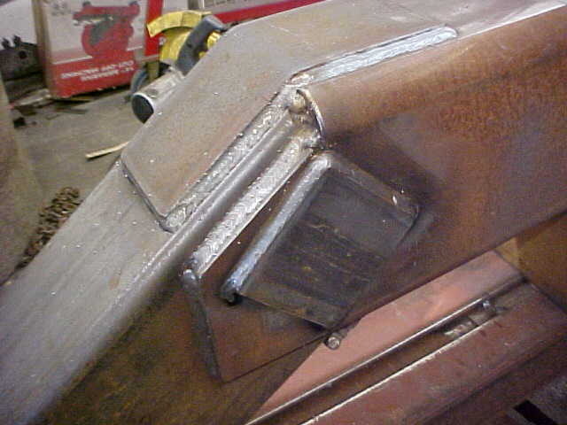
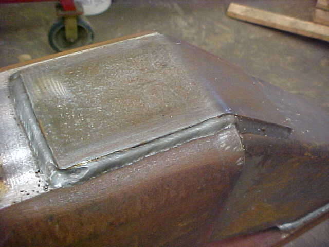
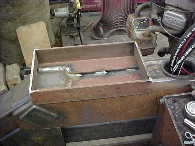
All the gussets done and installed. I'll do the rest of the welds when I disassemble and roll it on it's side.

MVC-019S_46.JPG


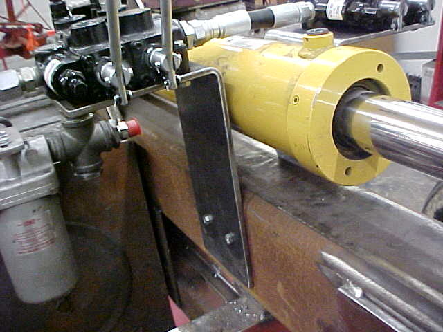
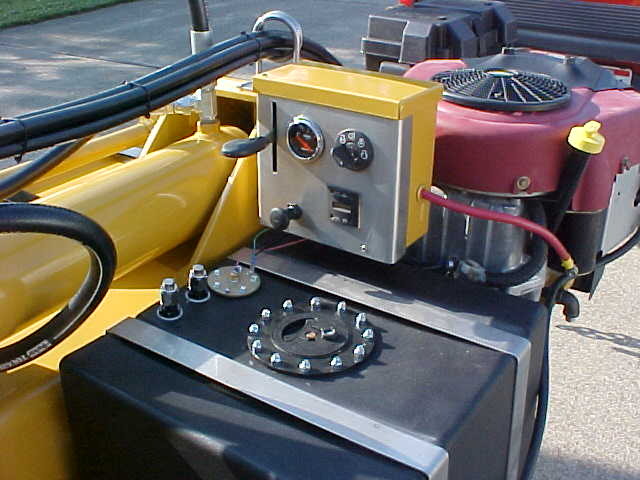
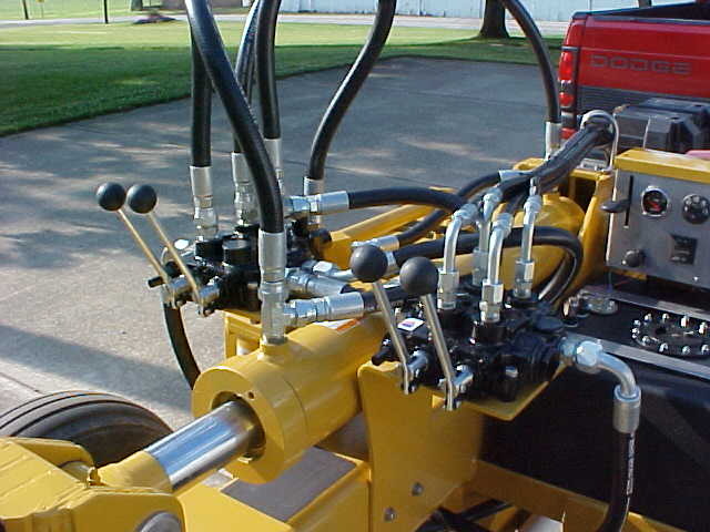
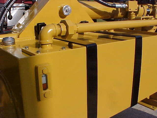
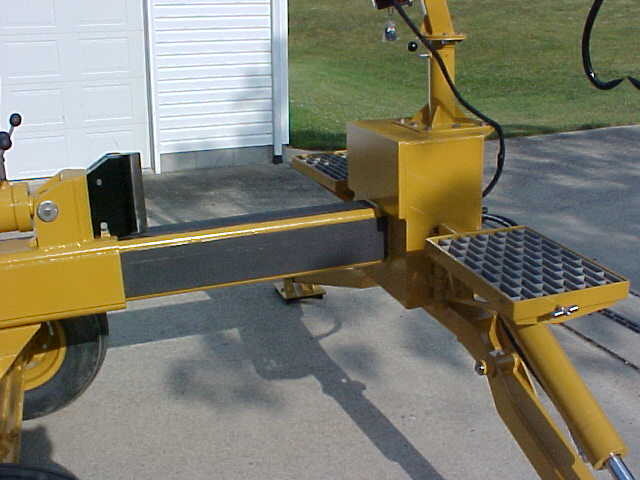
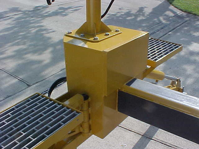
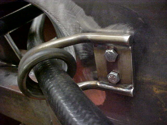
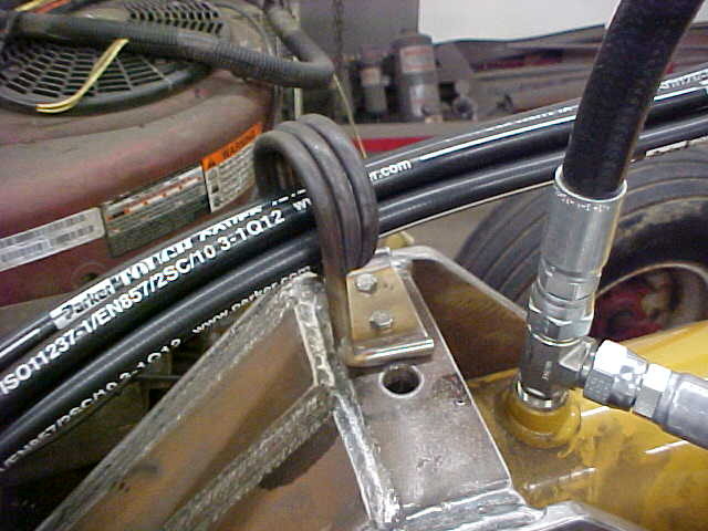
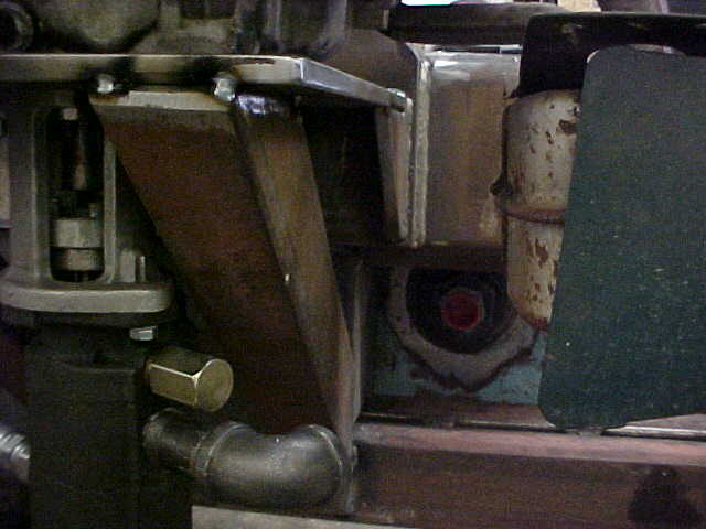
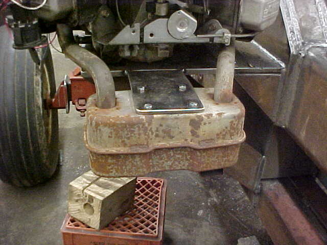
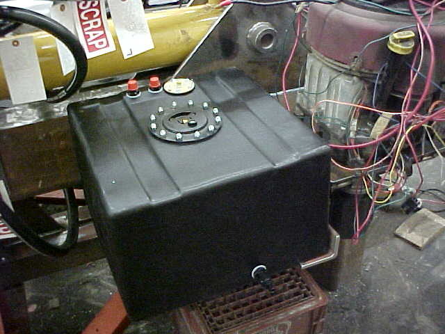
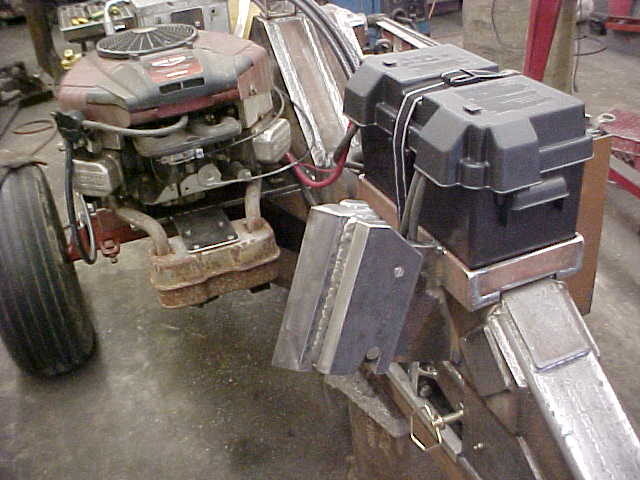
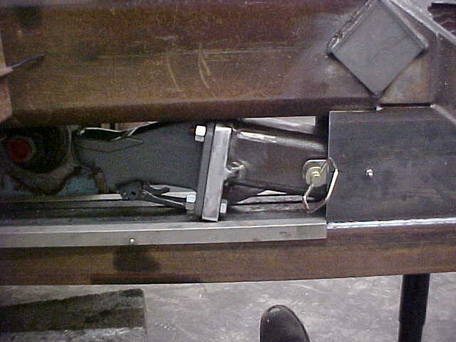
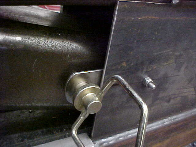
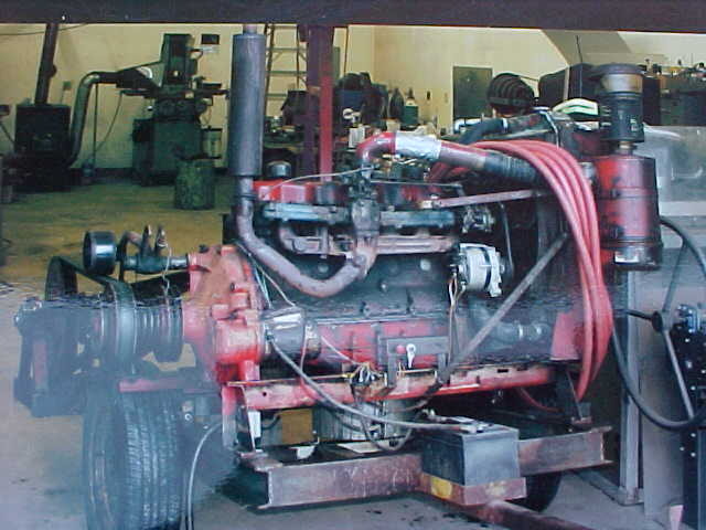
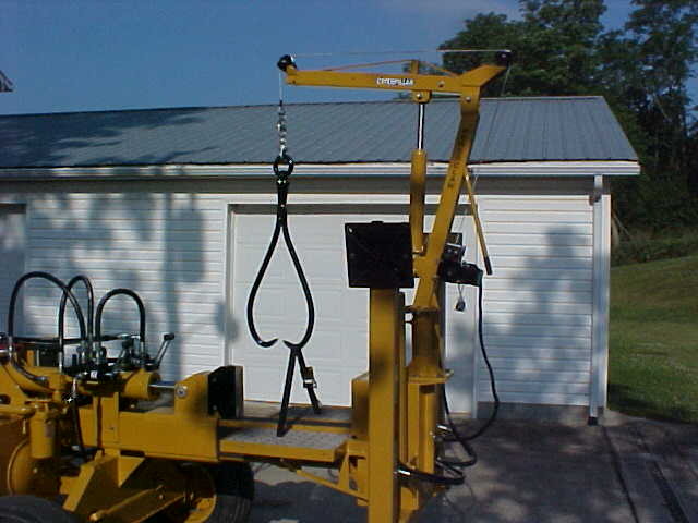
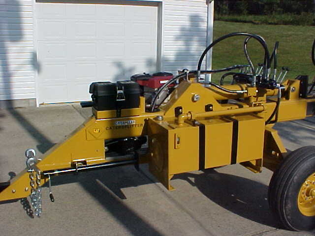
For the valve mounts I just bet up some 3/8" plate that's 6 inches wide. I wanted the valves in a position where you could work them from either side but not be in harms way.

MVC-020S_36.JPG


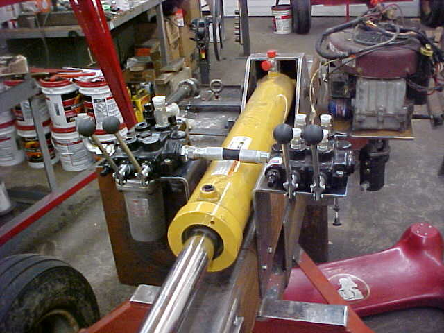
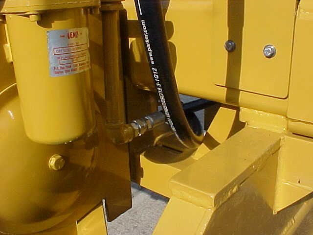
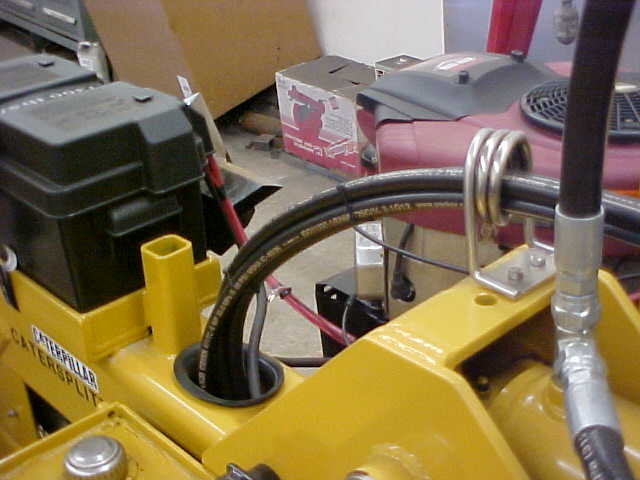
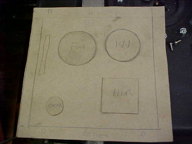
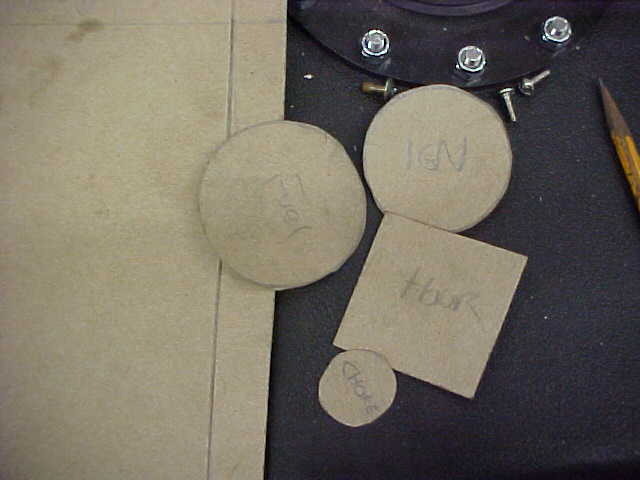
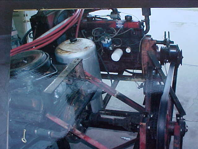
I bolted these on as I know from the past, sometimes you might want to "adjust" things. The layout of the hydraulics is the most mind challenging aspect of this for me. Trying to figure out the position where it will line up is a pain sometimes. I did a drawing of where each line goes to help me out.
 
MVC-018S_48.JPG


I'm routing the hydraulic lines for the stabilizers through the main box beam. Needed an access so I used a 3 1/4" hole saw and drilled the holes. Took awhile with 1/2" steel as I kept cutting oil on it to save the hole saw.

MVC-019S_47.JPG


Ground the edges to straight and smoothed them out. They'll be 4 lines plus the electrics for the winch going through here.

MVC-020S_37.JPG


You always wanted to avoid wear points if possible. I slit some hose down the length and rolled it in place. Keeps itself there but if I see something better I may change it out.

MVC-021S_27.JPG


Made up a gusset brace for the axle to beams and welded it in. Should be good to go here now.

MVC-022S_19.JPG


Hose from the pump to the auto cycle valve runs through this space. I relieved the corner of the box and inlaid a section of big pipe. Welded and smoothed it makes for a tidy run. I'm going to make a hose hanger here as well.

MVC-018S_49.JPG


Got some 3/8" stainless rod and heated it up. Bent it around a large piece of round stock for a hose holder.

MVC-019S_48.JPG


I then got the stand off height measurement I needed and bent it there. I then TIG welded a small plate between the rods and cut them off. Drilled a couple holes in it for mounting.

MVC-020S_38.JPG


Put it in place and marked the holes. Drilled and tapped them so it's simple and clean. I'll clean them later and leave them bare.
 
MVC-021S_28.JPG


Made another one with a triple loop for the 4 hoses that run to the outriggers. Keeps everything tidy.

MVC-018S_50.JPG


I used some smooth bore field tile inside the main box beam for the hose runs. There are some bolts sticking through the beam and this way the hoses will be safe from wear spots. You can see the conduit for the electric run for the winch as well. Going to make a coverplate next for this end.

MVC-019S_49.JPG


Threaded 2 holes into the 1/2" box beam to hold the cover on. Glued a threaded connector onto the conduit. A threaded weather seal connector holds the pipe in place, quick and simple. I'll tie the hoses when it's all painted.

MVC-018S_51.JPG


With the lines in place I knew the clearances I have to deal with so I made up the outer braces for the motor mount. Used some heavy angle iron and tacked it on.

MVC-019S_50.JPG


Made up a mirror image of the first one for the other side. Had to inset it a little so it would be flush with the bottom rail. Better for the suction side line as well.

MVC-020S_39.JPG


Was wondering what muffler system I would use and thought I'd have to start from scratch. Started looking and found I could use the stock one with a simple bracket. Put an angle brace below it as well.

MVC-021S_29.JPG


Here is the muffler attached and I can use the safety shroud as well with it.(not shown here) Was happy this worked out so easy.

MVC-022S_20.JPG


While we're on safety stuff: I made up some hook points to hold the arms up while transporting. Simply attach to the pins on the stabilizer feet. I'll run a strap up through the hoist arm to hold it in place at the same time.
 
MVC-018S_52.JPG


Next was to do the hitching points. I want a heavy ball and hitch pin set up depending on what I'm pulling it with. Doing an oversized Reese type. Cut out and drilled the pieces for the hitch pin one here.

MVC-019S_51.JPG


Measured the offset needed for the truck and tractor and made the offset accordingly. This way the splitter will be level when using either while using the same hitch. Welded it all up and one 1 inch bar extends into the tube enough for a lot of weld in the inside.

MVC-020S_40.JPG


Here it is cleaned up and this position is for the truck. 2 5/8" bolts will hold it in position.

MVC-021S_30.JPG


This is for the tractor drawbar. I'll make another box up to mount the ball coupler to. Waiting on it to arrive at the moment.

MVC-022S_21.JPG


Got my fuel tank which holds 12 gallons. Welded on some angle to basically trap it in position. I'll make up some straps as well.

MVC-023S_14.JPG


Needed some mounting points so cut a piece out. Ready for welding here, after double checking measurements.

MVC-024S_9.JPG


Welded in and smoothed. Put a support in the center as well while I was at it.

MVC-025S_7.JPG


Got some stainless strap and bent them up using the bender. Makes really nice repeatable bends cold.
 
MVC-026S_6.JPG


Used some 1/2" blocks on the ends and drilled/threaded them. I then TIG welded them to the straps. Here it is all installed.

MVC-027S_5.JPG


Here is a close up of the attachment mount.

MVC-028S_4.JPG


Up next is the control box for the switches, gauges and such. I'm using an old electrical box and needed a mounting surface. Got some heavy strap and bent a 90 in it using the press.

MVC-029S_2.JPG


Not really a whole lot to deal with but made a pattern out of cardboard and cut out patterns for the other things as well. This way I can move them around to see what will work out best in actual size.

MVC-030S_1.JPG


Loose patterns make it a lot easier and you can change the design quickly. When it right, just tape them down.

MVC-031S_1.JPG


Bent the front panel from some stainless sheet and mounted everything up. Turned out pretty nice and clean.

MVC-032S_1.JPG


Ball hitch receiver came in so I could make it up as I knew the measurements. Bottom bolt mounts had to be recessed for the hitch point to be right, 1 inch plate leaves plenty of strength.

MVC-033S.JPG


Grabbed some scraps and cut out some small triangles for strength gussets. Quick and easy. On small stuff like this it's easier to mount the straight edge in the vise and clamp the piece to it for straight cuts.
 
MVC-034S.JPG


All done and ready to go. 5/8" bolts for attachment.

MVC-035S.JPG


Using left over angle iron for the battery box mount. Ready for final welding here.

MVC-005S.JPG


Mounting it to the top of the beam for easy access. Once I was happy with location I welded it down. Left the ends open so water and such won't get trapped.

MVC-009S.JPG


I'm using a plastic marine battery box and need to have a way to hold it all down in place. I plasma cut some slots in the angle to allow a strap to be fed through.

MVC-010S.JPG


Strap feeds under the box and over the sides, Overkill but it'll keep everyone happy for transport.

MVC-011S.JPG


I don't like the strap that came with the box so I'll probably switch it to a ratchet style later.

MVC-012S.JPG


Made up a mount for the extra wedge. Wedge rocks back and rests on the mount. One pin with a spring pin will securely hold it in place.

MVC-013S.JPG


Poly centrally locates it and keeps the rattles down. Set screw hold the lower pin in place.
 
MVC-014S.JPG


All done but the pin here. Not OSHA approved with the exposed edge!

MVC-006S.JPG


Since I'll always have one hitch not being used, I needed a storage space. There was and opening on the front where the beam goes down and decided to use that. 2 simple straps on both sides swing for adjustment and hitch pin with spring pin traps it all in place.

MVC-007S.JPG


Close up of how it works.

MVC-008S.JPG


Got a side handle lift jack and welded the mounting plate on. Side handles are real nice and save busted knuckles when mounting in situations like this.

MVC-015S.JPG


I'm using a 30 inch stroke cylinder. We normal cut 22 - 23 inches long and needed a stopper to save the wasted stroke. Nice to have the extra for occasional long ones but most time it is not needed. This is what I came up with. 2 pieces of angle welded on the bottom with an open slot in the middle.

MVC-016S.JPG


Used a piece of heavy plate and welded a "key" in the center. This way you can slide it in and out with no tools and it will stay in place when not used. You can make up more plates in different sizes if needed as well.

MVC-017S.JPG


This way the box slide can come all the way back when not in use. Nothing rides on the ram like a slip collar and it's quick and easy.

MVC-018S_53.JPG


In place and you can see what I was going for. Should be bulletproof.
 
MVC-019S_52.JPG


With all the stuff in place I tore it all down and flipped it over for final welding. Got a little weight here but did it all by myself.

MVC-020S_41.JPG


One little detail I did was mark where the oil filter was and drilled a drain hole. I then ground a "funnel" area to the hole which will keep it a little nicer when changing the oil.

MVC-021S_31.JPG


I sand blasted everything completely bare and painted it in pieces. Did 3 rounds of this over the course of 3 days. Got a friends homemade compressor which made it go a lot better.

MVC-021S_6.JPG


He has a industrial Ford 6 cylinder for a power source. Thing purrs like a Kitten and you just run it at idle.

MVC-022S_24.JPG


Taking a pic from a pic so please excuse the quality here. Goes to a gear reduction and slows it down more via a large belt. I believe he said it came out of an old combine.

MVC-023S_17.JPG


Power is then used to spin a large V8 motor. Yes, he uses all 8 cylinders for pumping and boy does it move a lot of air. He has a radiator and functional water pumps on both motors keep the temps down. He uses it to blow his leaves in the fall....in a hurry!

MVC-022S_22.JPG


Painted it all outside and moved it in once dry. It'll get scratched up soon enough!

MVC-023S_15.JPG


Here it is all together. Test run all checked out with no leaks and everything worked well. Will do some splitting and testing soon.
 
MVC-024S_10.JPG


Using 2 straps as I changed my mind here for transport. One locks the tables and the boom hook while the other is the safety for the stabilizers.

MVC-025S_8.JPG


33 gallon hydraulic tank and I put on safety chains as well to keep it all safe. they will get hooked to truck when on the road ;)

MVC-015S_1.JPG


Stainless holder keeps the chains off the ground and splitter at the same time when not in use.

MVC-026S_7.JPG


Added a carrier for a pole light when working at night or a dark barn. Tarp strap holds it in place when not in use.

MVC-027S_6.JPG


Slide limit shown here and no way to loose it in transport when it's locked back.

MVC-028S_5.JPG


Control panel can easily be reached from the working/splitting position. I upgraded the battery cables to a bigger size than stock for reliable cranking.

MVC-029S_3.JPG


Auto cycle on left and the 2 spool for the stabilizers on the right. Both reachable from either side.
 
MVC-030S_2.JPG


Here is the finished wedge holder pin with the 4 way on it.

MVC-031S_2.JPG


Hoses out of harms way as much as I could do.

MVC-016S_1.JPG


Gotta have some fun with the decals;)

MVC-017S_1.JPG


Bypass in the top right hand corner keeps the fluid from going through the valve on return. Saves wear and tear on it and was recommended by P and J.

MVC-018S_54.JPG


With this wedge design I don't believe I'll need stops on the backside if a piece gets stuck on the ram. The reason is it's 24 inches from the wedges cutting edge to the valves when returned to open. If I was selling I'd put one on but for personal use we'll be able to manage. I can always add if needed too.

MVC-019S_53.JPG


Limiter easily slips out. The black paint on the sliding surface is graphite paint. Makes it real slick for initial start up but wears off. You can repaint but I've found once you get past the start up you're fine.

MVC-020S_42.JPG


All spread out and it's about 11 feet wide in this position.
 
MVC-021S_32.JPG


Good shot of the graphite paint and the tables out. They will come in real handy and save a lot of bending over.

MVC-022S_23.JPG


Won't look like this for long.

MVC-023S_16.JPG


Hose routing through the main frame.

MVC-024S_11.JPG


Here is the overhead light in place for those late nights. On the lift arm you can see the cordless winch too. That should save the back too.

MVC-019S_55.JPG


Light pole sits in the box tubing shown here. Nothing fancy, just easy and reliable. I used quick connects of the wires.

MVC-018S_56.JPG


Here's the "Powerclaw" close up.

MVC-025S_9.JPG


Lots of room in there and you can stand towards the valves for safety if something pops. From our experience I'd rather have the wood be able to move a little that to add the stress in the splitter.

MVC-018S_55.JPG


Here is an action shot. These are Beech and just over 3 ft in diameter. Sure saves the back but I am always leaving an escape route. Don't want to be in between steel and one of these rounds falling, they'd win.
 
MVC-019S_54.JPG


These were cut last Winter as 2 trees fell out into the field. We bucked them up and moved them with the backhoe to a spot in woods. I was saving these to play with ;)

MVC-020S_43.JPG


Biggest one is about 4 1/2 ft at the crotch. You have to plan a little as you can put the partial chunk on each of the tables and hold a piece with the tongs. Getting used to it now and we don't let any of the chunks hit the ground to save lifting.

MVC-021S_33.JPG


When we were doing the smaller chunks in the barn we were getting over a cord/hour, stacked. The big ones slowed us down as we were here 2 1/2 hours. There is a stack on the right side about the same as the left. The best part is my back isn't sore and don't feel tired. Mission accomplished.

I really liked doing this project as it had been in the planning stages for years. Nice to see it all come together and work ;) I have just under $6,000.00 in it. Yes, Quite a chunk of change but will probably be the last my lifetime. Used steel prices have gone up a lot here recently and I bought most of the hydraulic stuff new as I wanted no question marks there. More scrounging could have made the price lower but I was working with what I had. Hoses and fluid have gone through the roof as well.

As I said at the start, You can get a smaller factory made for less, but I wouldn't have gotten the features I wanted. Try splitting a 4 ft diameter, 24 inch long Beech round with an inertia splitter and report back ;)

Thanks to all for the kind words and hope this has helped answer some questions or gave you some ideas to steal. I'll try to get some better action shots in the future. Kept forgetting to get them as we were having fun!

Special thanks to P and J Commercial Products. James was always quick to return calls and answer any questions I had. Top of the line company with nice stuff.
 
I just went back and read through the whole thread and that's a huge amount of work and time, and steel. Excellent work, straight and tight and hell for stout. I don't know if you could buy something that thoroughly reinforced. The only part I wonder about lasting forever is the pawl mechanism on the swinging tables. Should be fine if the table is always still when engaged, but if the table is moving even slowly with a heavy piece on it and the gear gets dropped in it seems like it would be like dropping a lathe into back gear before it stops completely. Had enough lathes come in missing bull gear teeth to know it happens. Not a problem if you always run it yourself.

Great project, great thread. No mysteries, you showed how and why you did everything. Thanks a million.
 
Absofreakingloutly awesome. As a guy that has built a couple of Tonka Toys (in comparison) I respect the amount of time, energy and engineering it took to make that thing come together. Just the planning stage alone must have consumed hours upon hours.

Very nice work and one helluva piece of equipment you have there. Kudos.:clap:
 
Kevin, I'm just curious if you considered a powered lift cylinder on the hoist instead of the manual one on it? When I've been considering adding a boom, I've been thinking 2 more valves and a hydraulic motor would make it power lift and swing. The thought of using a hyd winch vs electric also crossed my mind, but maybe I'm just getting carried away. Running the extra hoses and keeping them out of the way would be a pain...

Any chance of your stroke limiter plate vibrating out if you're not working on level ground?

That's about all I really question after the whole build. I'm sure if I were doing it, there would be more than that to question in the first post, let alone the whole thread. Great work!
 
I just went back and read through the whole thread and that's a huge amount of work and time, and steel. Excellent work, straight and tight and hell for stout. I don't know if you could buy something that thoroughly reinforced. The only part I wonder about lasting forever is the pawl mechanism on the swinging tables. Should be fine if the table is always still when engaged, but if the table is moving even slowly with a heavy piece on it and the gear gets dropped in it seems like it would be like dropping a lathe into back gear before it stops completely. Had enough lathes come in missing bull gear teeth to know it happens. Not a problem if you always run it yourself.

Great project, great thread. No mysteries, you showed how and why you did everything. Thanks a million.


The gears are hardened and that was on my mind as well as far as tooth loss. What I did to combat it is to grease them well and make the springs fairly weak. You can rachet the tables without using the release handle but I try not to. I agree, probably a better solution but it has worked well so far. Like you said, I'd rather it be able to move than be rigid as something WILL give. I may grind end up grinding out a gear from softer material if needed.
 
Kevin, I'm just curious if you considered a powered lift cylinder on the hoist instead of the manual one on it? When I've been considering adding a boom, I've been thinking 2 more valves and a hydraulic motor would make it power lift and swing. The thought of using a hyd winch vs electric also crossed my mind, but maybe I'm just getting carried away. Running the extra hoses and keeping them out of the way would be a pain...

Any chance of your stroke limiter plate vibrating out if you're not working on level ground?

That's about all I really question after the whole build. I'm sure if I were doing it, there would be more than that to question in the first post, let alone the whole thread. Great work!

The reason for not having a powered lift cylinder was cost, weight and loss of reach. I can lift the front end up off the jack and sometimes on rough roads it bangs a little. When I took it across the local scales it weighed 3990 lbs.

The manual cylinder on the boom is not used at all. I may put a solid rod in there if it starts leaking. I just left it on as it gave me a little cushion on log position. The winch has 30 feet of reach so I can drag chunks to it and not have to move as much when backing down a tree's length. If you notice there is a handle on the boom that you can spin it with. I find I don't use it much as a hand on the log and the other on the cordless remote seems to work well. The winch is a little slow but honestly, it's safer that way and is fast enough for me. I normally was winching one up in position while Dad was finishing up the smaller chunks. Kept everything moving well.

On the plate, most of our ground it fairly level. The stabilizers will level it out pretty close. Haven't had it move out yet and normally it doesn't stay on the outstroke long enough for it to happen. Auto return is NICE! ;) If it does happen a simple screw in eye on the axle face and a welded nut on the limiter is all that would be needed. Just use a tarp strap to hold it. If we were running 16 inch long stuff occasionally I'd make up another limiter that size. We don't sell much so it probably won't happen.
 
Back
Top