Conveyor build

Arborist Forum

Help Support Arborist Forum:

This site may earn a commission from merchant affiliate links, including eBay, Amazon, and others.
MVC-004S_9.JPG


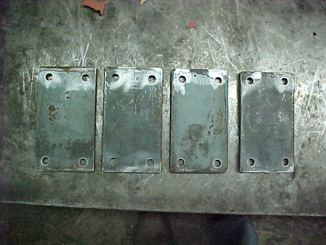
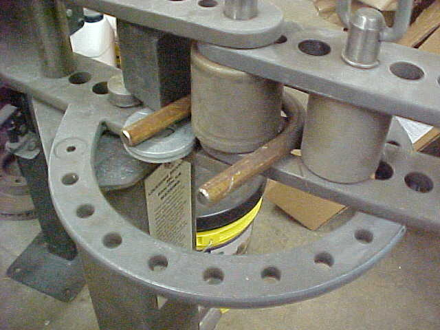
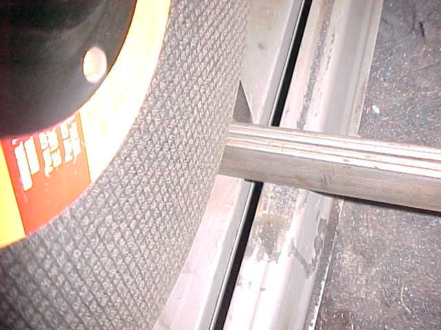
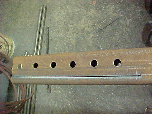
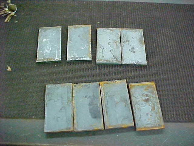
Once they were all drilled, I used the plasma torch to rough cut to length. I'm going to round the open end so leaving it long. Just quicker to cut this way and less wear on the chop saw blade.

MVC-005S_7.JPG


All cut up and ready to round the open end. I'll cut a short piece of round stock, center drill a 5/8" hole and bolt it to the bracket. I'll blend it out using the method shown before. Takes a little time but gives it a nice finish touch.

MVC-006S_7.JPG


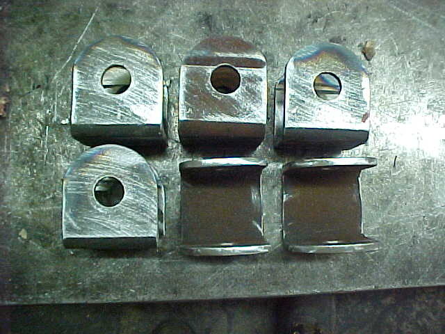
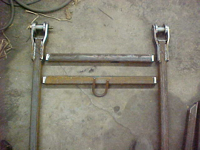
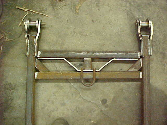
Got those all done and cleaned up. I'll work on the arms next. I have to make up some solid pivots for the ends that will be welded into the box tubing and will keep the wear to a minimum.

MVC-007S_6.JPG


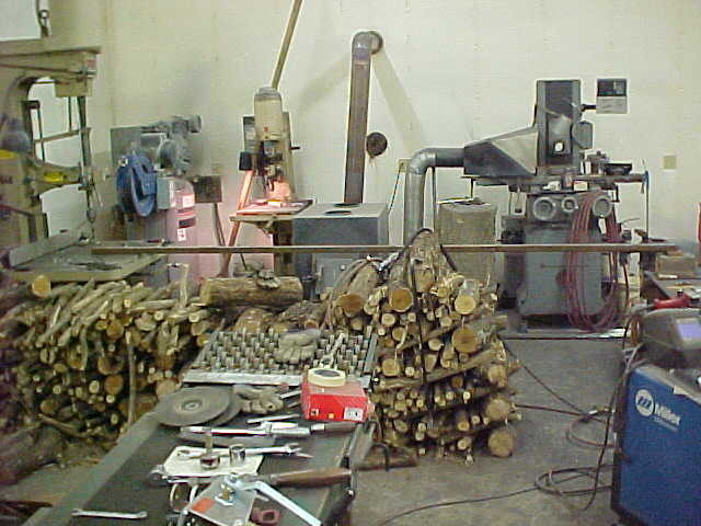
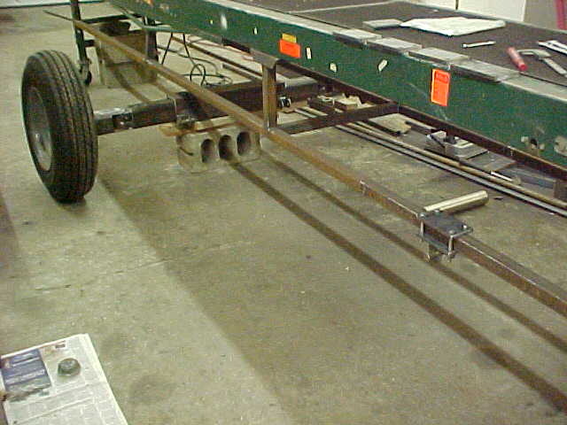
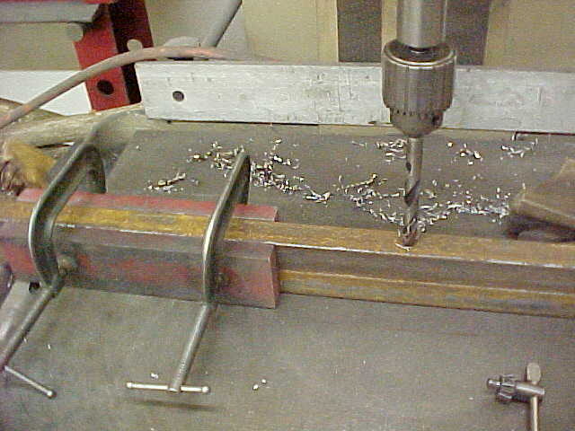
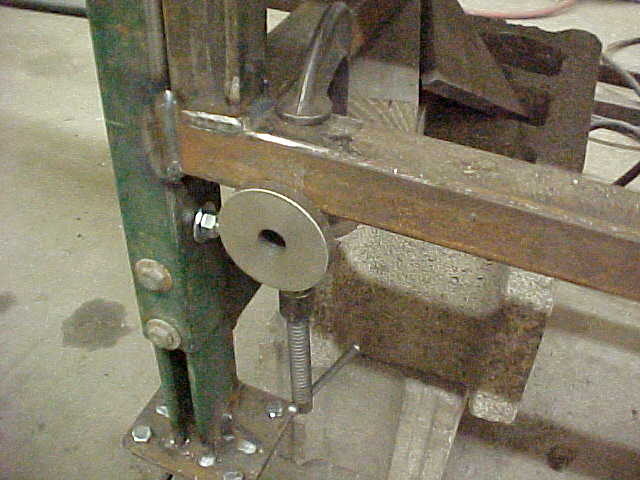
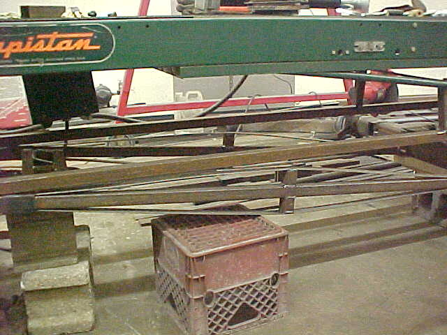
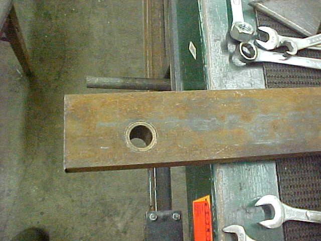
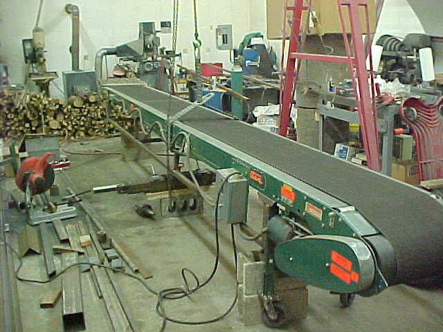
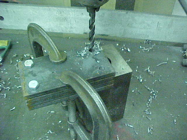
Marked the hole for the pivot and drilled it out. I'm drilling into a long bar and want them straight so I supported the far end and brought it to level with the table. Keeps everything straight that way. You can see I'm getting rid of the honeysuckle in here! Doesn't take but a few pieces to keep the shop nice.

MVC-001S_10.JPG


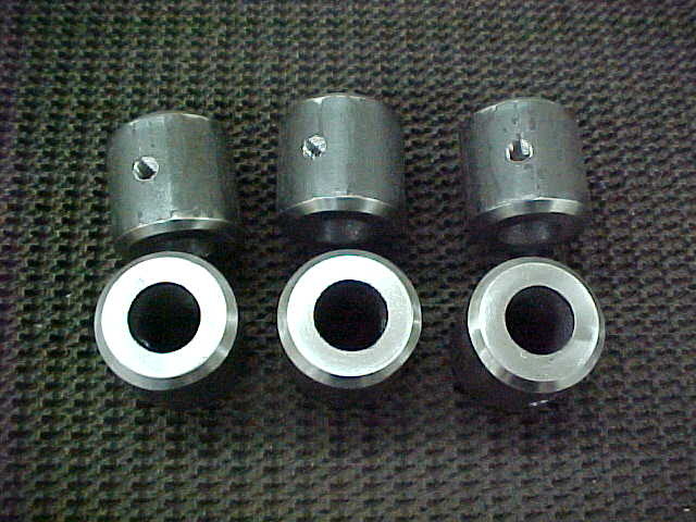
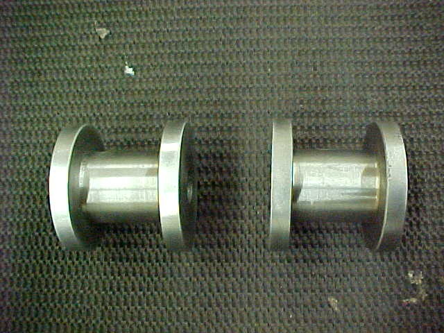
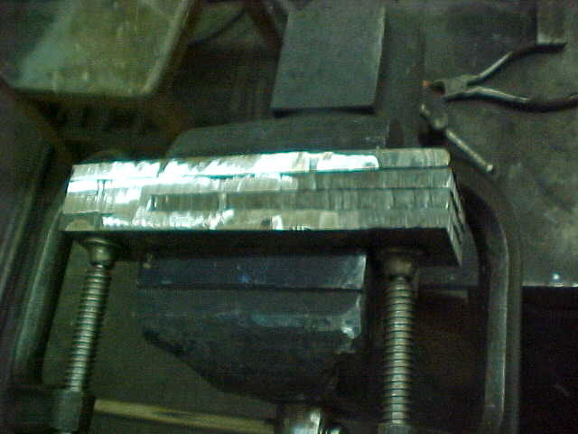
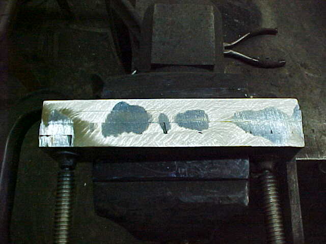
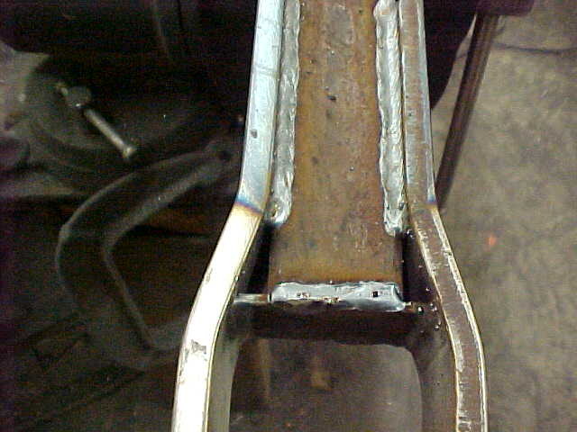
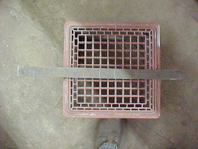
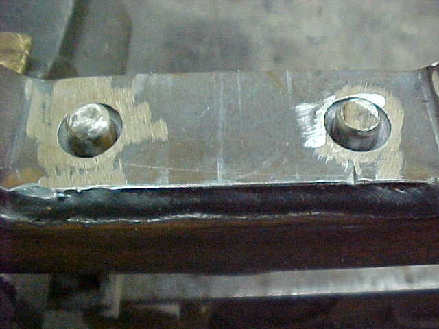
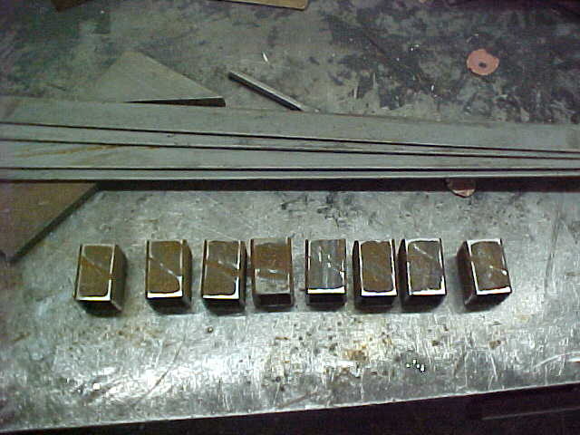
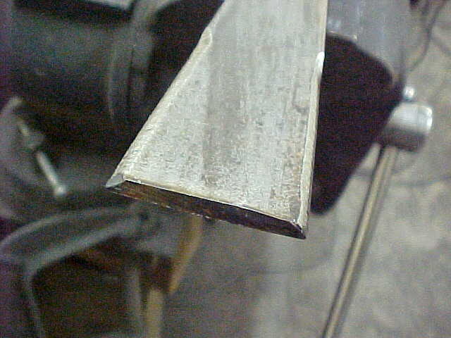
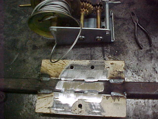
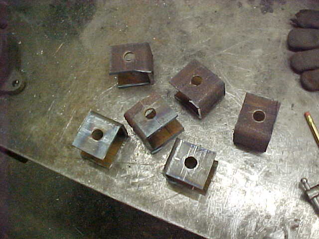
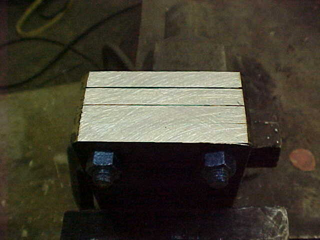
These are the bushings I'll weld into the ends of the box tubing. Made them out of bar stock. I chamfered the ends so when I grind them flush there is still weld there.Also drilled/tapped them all for zerks.

MVC-002S_10.JPG


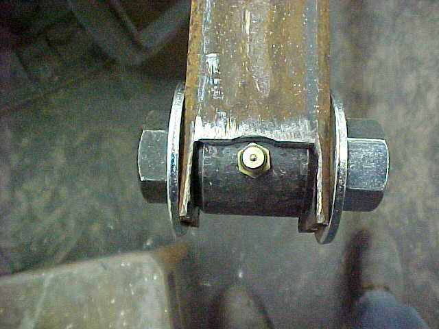
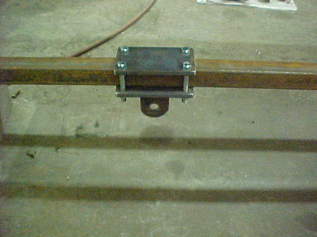
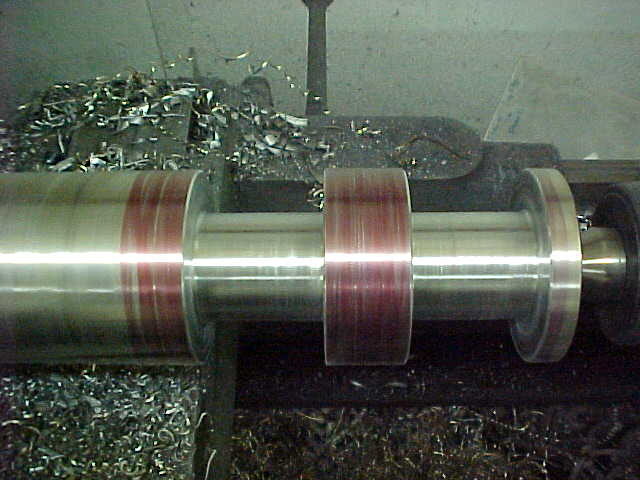
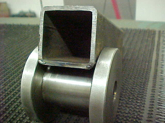
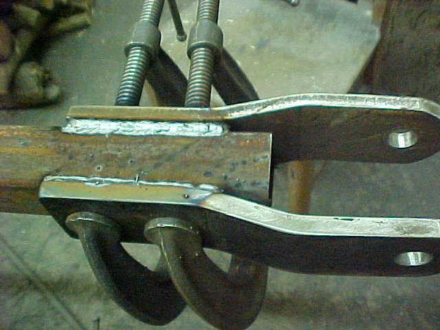
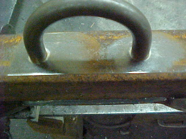
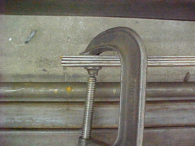
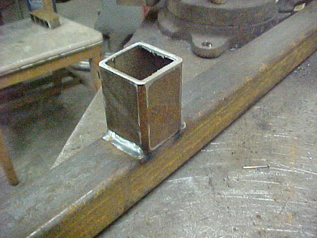
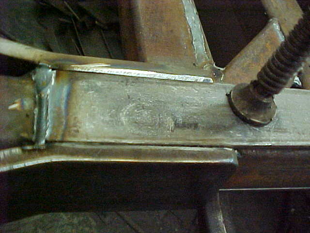
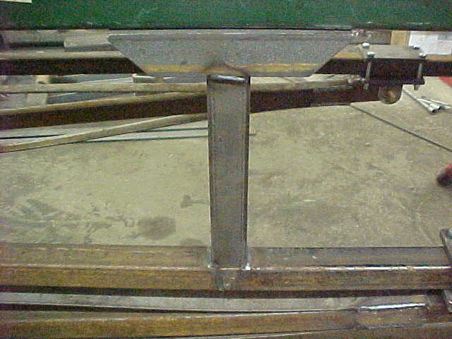
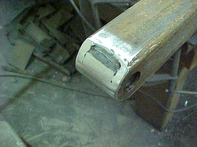
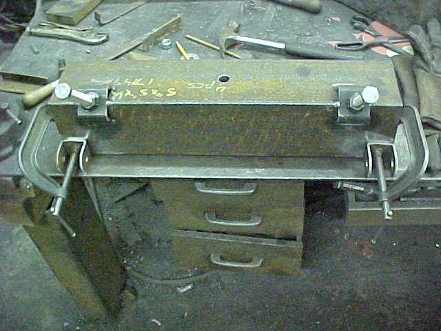
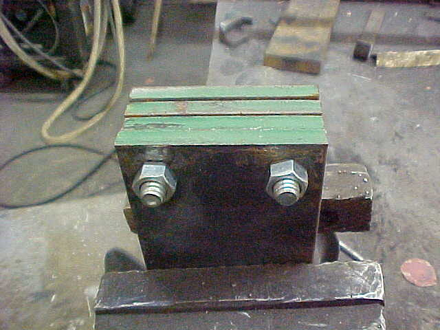
Recessed the tubing and held it all in place with a 5/8" bolt for welding. this way everything stays true and tight. I'll grind away the excess.

MVC-004S_10.JPG


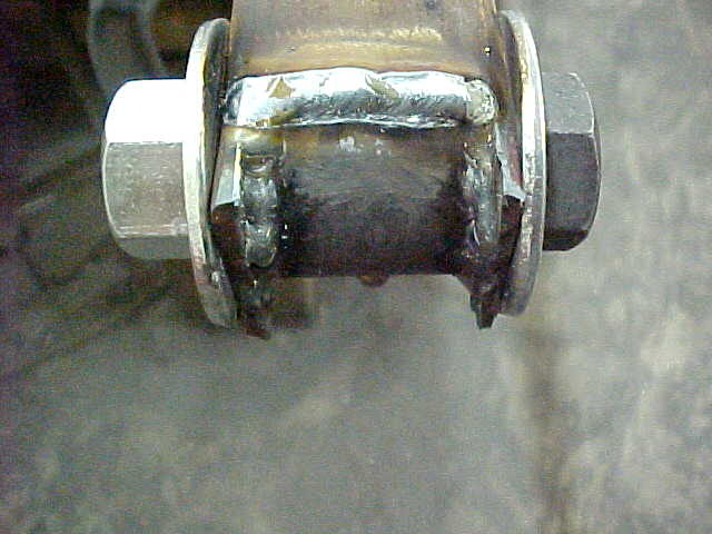
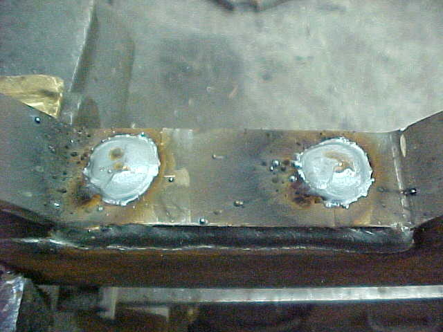
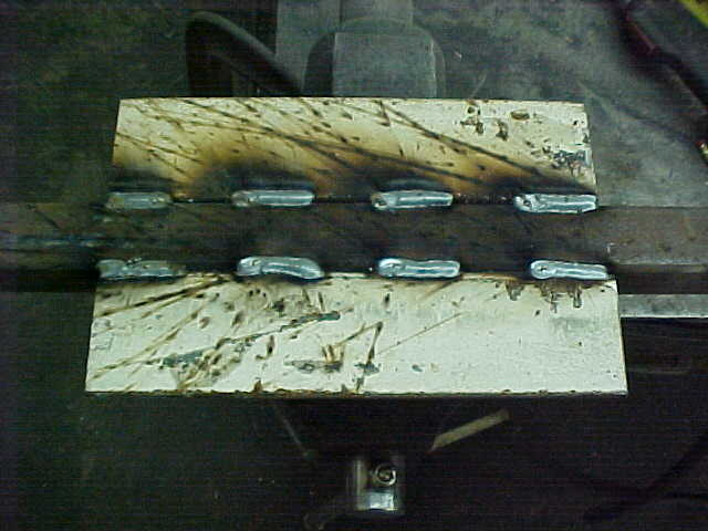
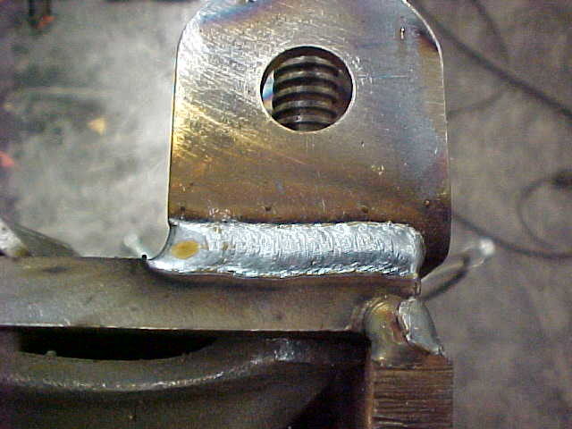
Quick welding here and it really is overkill but I want them solid.

MVC-005S_8.JPG


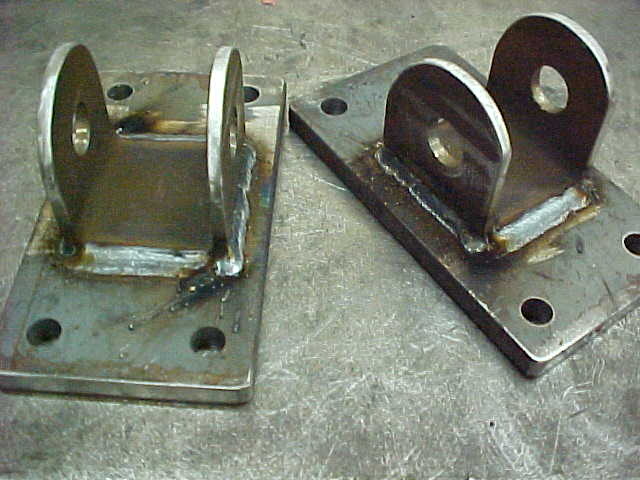
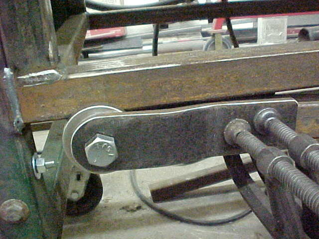
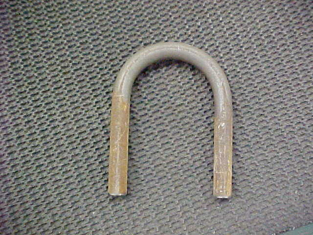
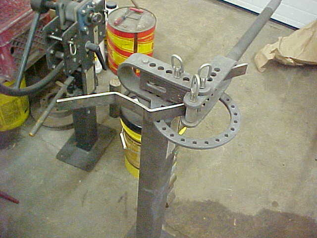
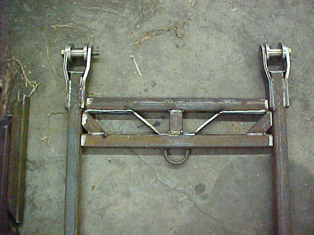
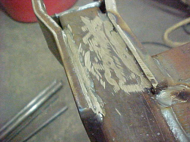
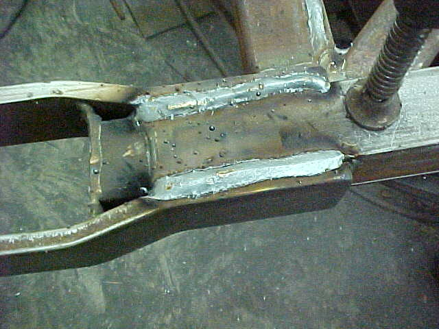
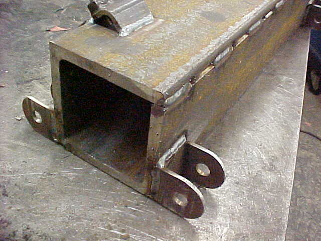
All blended out and ready to go. This way everything clears the mounts when it swings and just plain looks better.

MVC-006S_8.JPG


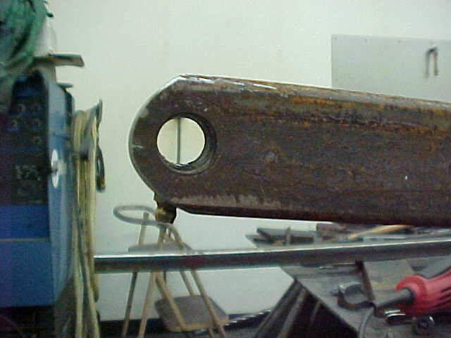
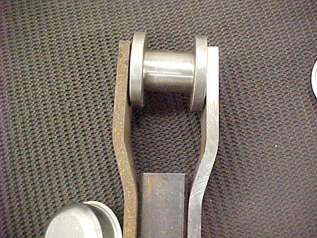
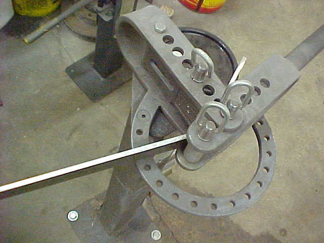
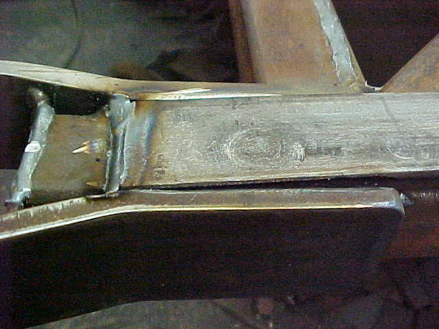
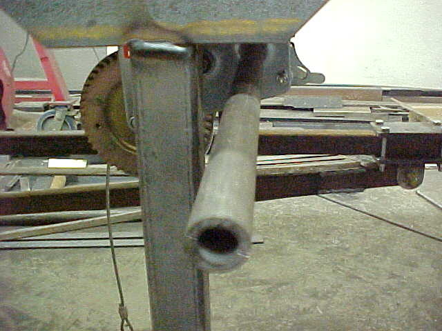
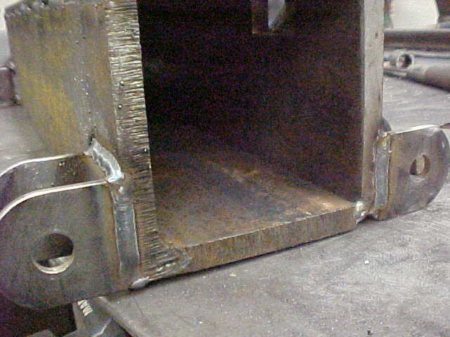
Here you can see the full radius and how it will be able to pivot.
 
MVC-007S_7.JPG


Next I had to determine the position of the axle so I needed to find the balance point. Lifted it a few time but got it. I'll use this as a center line on where to put the axle. Still have to add the hitch, jack and such at the end so it will be front heavy as it should be for towing and such.

MVC-008S_5.JPG


Pulled the axle out and i'm going to weld the pivot brackets on. I want them as low as possible so I have as much of an angle as possible. This will make raising and lower it easier than if it is close to flat with the conveyor. Laid it on the bench and squared everything up before clamping them in place.

MVC-009S_3.JPG


Welded them all up on all four sides.

MVC-010S_4.JPG


A little later I realized this was a mistake. You need to have the front a solid mount otherwise the axle will flop over.

MVC-011S_4.JPG


I had to cut one of these off and weld the tube on. You'll see this set up for a while then it will change. Made a boo boo there!

MVC-001S_11.JPG


Now for the slide brackets for the other end of the lifting arms. Local used steel supplier sells by the pound and the have an extremely well organized place. had the ready cut smalls laying there so I snatched them up.

MVC-002S_11.JPG


Marked a single piece first and drilled it out for a pattern. Looked good so I grouped the closest sized pieces and drilled them in sets of 4. Keeps everything the same and goes quicker. Once 2 holes are drilled I bolt them together for sameness.

MVC-003S_12.JPG


Once all drilled and bolted, I true up the ends to make them the same. Easier as a group because you can see the flatness come in. 9 inch body grinder makes quick work of it.

MVC-004S_11.JPG


I rough them in with an old wheel then lay a new wheel flat faced on the end. Does a nice job as you can see. Every so often I run a cluster diamond over the surface to keep the glazing off of and the cutting going on.
 
IMG_0010.jpg Again not sure what direction you are going. With mine the axle yoke pivots towards the tongue end and raises and lowers towards the high end with a manual jack and some adjustable pin points on a slip tube. What happens with this design is the axle moves forward and rearward in relation to the center, or midpoint (edit: should read balance point) of the conveyors length, changing the balance point. At full height the tongue weight is very light. Wood moving up the belt can then tip it. When lowered the axle pivots to the rear increasing tongue weight, more than I can lift and want on the solid axle of my quad. I have know idea if this applies to what your doing or not.
Edit: This is the best photo I could come up with from what I had.
 
View attachment 407928 Again not sure what direction you are going. With mine the axle yoke pivots towards the tongue end and raises and lowers towards the high end with a manual jack and some adjustable pin points on a slip tube. What happens with this design is the axle moves forward and rearward in relation to the center, or midpoint, of the conveyors length, changing the balance point. At full height the tongue weight is very light. Wood moving up the belt can then tip it. When lowered the axle pivots to the rear increasing tongue weight, more than I can lift and want on the solid axle of my quad. I have know idea if this applies to what your doing or not.
Edit: This is the best photo I could come up with from what I had.

I thought about doing it like that and I guess my gut was right on what would happen. What I'm planning "should" put more weight to the front. It will be adjustable as well for weight transfer too if needed. Hard to explain but it'll come to light eventually. Thanks for the input! I'll probably use mine more as as a level table to reach into buildings and such.
 
MVC-005S_9.JPG


Corners rounded and smoothed here. I'll now weld the brackets on 2 of them.

MVC-006S_9.JPG


Brackets on and they are done. I'm making them bolt on so I can adjust if need be. Once I have exactly where I want I may drill a single hole to bolt through to lock in position.

MVC-001S_12.JPG


Mounted the bracket on the rail and gave myself some adjustment room on both sides. Always good to have a plan B if need be.

MVC-002S_12.JPG


With the bracket ready I can now measure and drill the front tube. I'll just drill it for now and wait to weld in the bushings till I have it all checked out.

MVC-003S_13.JPG


With the 2 finished ends bolted together I drill the opposite end. I used 2 pieces of heavy stock and C clamps to hold the other end straight.

MVC-004S_12.JPG


Slid some bolts in so next is the back. I need to make up some Spool type rollers to slide on the 1 1/2" rails. I'll turn them out on the lathe.

MVC-005S_10.JPG


Had some 3 inch diameter stainless so I made them out of that. center drilled the end and started working it all out. .375 shoulders and here I'm basically done. I'll drill the 5/8" hole in the lathe as well.Edit

MVC-006S_10.JPG


Cut them off and skimmed the ends to bring in the .375. Added bonus I'll have no rust issues since they're 300 series stainless.

MVC-007S_8.JPG


Should keep the tube captured pretty well. I allowed some clearance for paint on the tube but it'll wear off fast.
 
MVC-008S_6.JPG


Clamped the spool at the furthest point possible. I'll take this measurement and cut these tubes to length. I can always shorten if need be. With on the fly making stuff I tend to like to have options.

MVC-009S_4.JPG


To mount the spools I needed some stout strap. Had some leftover 3/8" that I had cut off something with the plasma. Had a nice cut side so I cut them to the same length. I want them the same and smooth so I'll use the 9 inch to true up the sides. Clamp them together first.

MVC-010S_5.JPG


After roughing in with the old wheel put on the newer full size and sprayed a dust coat. Lets you see the lows better. Ran it over a few times holding flat and when it stops cutting nice I skim a cluster diamond over the surface of the wheel.

MVC-011S_5.JPG


In less than 5 minutes you have decrease your scrap pile and found a use for some steel on hand.

MVC-012S_3.JPG


All four pieces are ready for next step. I need to bend some offsets in the as the spools are wider than the tubing. This is why I went with heavy pieces for this. I need a 1/2" offset on each side. Could weld spacers but I have another idea.

MVC-013S_4.JPG


Got 2 pieces of 1/2" scrap stock and put them opposite of one another. Then used 2 large chunks of hardened tool steel above and pressed it with the 40 ton. Put layout lines on it so I should be able to make them all the same. Steel doesn't argue with the press!

MVC-001S_13.JPG


Got all the strap bent and the same. I'll now drill them out and round the corners.

MVC-002S_13.JPG


Threw the spool in there to double check and looks good.

MVC-003S_14.JPG


Put the arm in position and clamped on the roller bracket assembly. I'll weld it up now that I now everything is lined up right.
 
MVC-004S_13.JPG


With the sides welded I'll make up a extended cap to tie everything together more. It'll also keep moisture/dirt from running down the tube as well.

MVC-001S_14.JPG


Caps are on so now I'm moving on to tying the 2 arms together and making an attachment loop for the winch cable.

MVC-002S_14.JPG


Got some 1/2" round stock and cut it to length. I've made up a chart over the years of what sizes are needed for ones I've done. Used the compact bender to them it cold.

MVC-003S_15.JPG


Makes real nice loops and fast too! I'm going to used tubing for cross braces and will drill through and weld this in on the backside of the tube.

MVC-001S_15.JPG


Cut a couple a pieces of tubing to length. I want to make it a double box if you will for more contact area and strength. This is the basic layout as I'll build this on the floor. I won't weld it to the arms until I reinstall it.

MVC-002S_15.JPG


Where the loop goes through I want more meat so I cut a piece of 3/8" out of some scrap and trued the edges. I then marked centerline and 4 bend lines.

MVC-003S_16.JPG


Put the 3/8" piece in the compact bender and bent the angles equal.

MVC-004S_14.JPG


Then bent the other ends till they were straight with the middle flat. quick and easy

MVC-005S_11.JPG


Here's all the pieces after cutting out a few more braces. Looks like it will all work so I'll tack and weld the center of the strap to the lowest box beam. I'll then drill the holes for the loop, while it's easy to do.
 
MVC-006S_11.JPG


Drilling like this allowed me to do it on the drill press. I then drove the loop through the holes. Makes for a very clean install.

MVC-007S_9.JPG


I ground angles on the loop ends and countersunk the 3/8" strap with a bigger drill bit. I'll now weld it all in place.

MVC-008S_7.JPG


This part is done and I don't think it'll pull out!

MVC-009S_5.JPG


Put it back on the floor, squared it up and C clamped it all up. Then tack welded it and rechecked squareness. Once it look okay I took it to the bench and welded it up. I'll now put it all back on to tack the center section to the arms to make sure it is all aligned properly.

MVC-001S_16.JPG


Put it all back in place and tacked it into position. Then pulled it all back off to bench weld everything.

MVC-002S_16.JPG


Completely welded up now so next is to make some "stretchers" as I call them to increase the strength of the square tubing. This will eliminate any flexing that could happen. I'm pretty sure the winch will not lift it in the clear down position as the arms are just too straight. I have to have the low level so I'm kind of stuck here.

MVC-003S_17.JPG


Local yard has some 1 1/2" strap surplus so for $20.00 I got eight 10 footers. I clamped 4 together flush at one end so I can cut them all at once.


MVC-004S_15.JPG


Makes them all the same this way and it is faster too.

MVC-005S_12.JPG


Cut 8 short sections of tubing all the same length as well and cleaned up the weld area.
 
MVC-006S_12.JPG


Marked the center and welded the upright shorty on

MVC-007S_10.JPG


Then on the one end I cleaned up where the strap will lay flat and beveled the sides where the strap will lay flush.

MVC-008S_8.JPG


Had to bevel the bottom of the strap as well because of the welded on roller brackets.

MVC-009S_6.JPG


Weld on the strap just on the end, letting it lay on the upright. See how it is angled towards the inside of the bracket?

MVC-004S_16.JPG


I use a C clamp to draw both sides in. This also "loads" up the strap giving it tension. When it is all welded together it makes the box beam way stronger because now it has to stretch the strap on the opposite side of the force.

MVC-005S_13.JPG


Welded in and just have to do the other end the same. Then I'll weld the center post to the strap.

MVC-006S_13.JPG


One side all done and installed. Everything looks real good so far.

MVC-007S_11.JPG


Did the other end in the same manner. With this all done, up next will be getting the winch mount done. The winch will be a safety and will raise it real high if needed. I'm planning on a bottle jack to raise it for the most part.

MVC-008S_9.JPG


Using previously made brackets on the bolt on side and decided to put the down tube where the splice was in the lower tube. Just added strength at the weakest point. It's about at the perfect location anyway.
 
MVC-009S_7.JPG


Cut and welded an upright on and did the same on the other side.

MVC-010S_6.JPG


I want to mount the winch in the center, under the belt so it is out of harms way. Used 2 pieces of heavy angle and welded them to a box beam.

MVC-011S_6.JPG


Ground it smooth and laid out where the winch will bolt to. Marked and drilled the holes while it was not installed. Just easier to do the drilling.

MVC-012S_4.JPG


Tacked the tube on and looks real nice. I'll put some angled braces in later but now I want to work on extending the crank handle. I want to have a nice solid mount so it doesn't flop around.

MVC-013S_5.JPG


Can't see it too well but I purposely mounted it so the crank's shaft was close to the upright. That way I can use a heavy piece of flat and just weld it to the upright and top bracket.

MVC-014S_4.JPG


This winch has 2 crank option and I'm going to use the slower on as it will make cranking easier. Doesn't need top be fast. It has a metric thread.

MVC-015S_3.JPG


I got a piece of pipe and tapped it with the correct size. I'll drill and tap for set screws on both sides later, once I know the length is right.

MVC-016S_3.JPG


Test fit look fine. I'm planning on using a solid shaft on the outside so I'll just weld that to the pipe. Crank end will have the most stress so I want that to be solid.

MVC-017S_3.JPG


Got a piece of 1" X 3" flat stock. Did my measuring and drilled a 1.250 hole. I'm going to use a oil impregnated Bronze bushing here for the crankshaft to ride in. Here it is pressed in flush.
 
What is the scrap yard asking for steel by the pound. I picked up a few pieces yesterday for 46 cent per lb. Don't know if I got the steel shaft or a good deal.

54 cents/lb here for normal stuff. Box tubing and box beams can go higher unless they get a lot they want to move quick. The yard is extremely well organized and sorted. Most uinder roof and a lot of it has no rust on it. Yeah, I'm pretty spoiled. I've been going there since I was a kid with dad and a lot has changed, for the better over the years. Yes, I'd say that is a decent price you got there, at least in our area.
 
I'm thinking I see what may or may not be an issue. That of axle mount tube rotation and lateral (side to side)movement as well unless x-braced in some way.

Bracing and gussets will be in place. This is just the set up stage of it. I learned not to do everything at the begining as sometimes things have to be changed for unseen issues. Backword engineering I guess.
 

Latest posts

Back
Top