Your ram is made differently than the OP. I agree with how you did yours and made mine the same way but the OP design will put the force sideways on the bolts - possibly breaking them off and binding in the 3/4" stock. Unless I misunderstood the OP, he cannot set his up like yours with the current ram design.That's a bad idea. Most rams have the top piece, a spacer and a wider piece on the bottom, all bolted down. Some use a few grade 8 bolts, others use 5+ soft bolts, that way if something does bind and keeps pushing, you will shear the bolts and not damage anything. It's a lot easier to replace bolts then to replace angle iron.
Here's an early pic of mine.
View attachment 458624
might be tough to see, but well there's 5 bolts.......one is out. But you can see the top piece, spacer and the bottom piece that keeps it from moving up an such. All bolts are soft bolts, found any any hardware store.
You are using an out of date browser. It may not display this or other websites correctly.
You should upgrade or use an alternative browser.
You should upgrade or use an alternative browser.
My log splitter build
- Thread starter 93green12v
- Start date


Help Support Arborist Forum:
This site may earn a commission from merchant affiliate
links, including eBay, Amazon, and others.
I didn't buy a diffuser. The guy that built my splitter made one. I only know that it points to the back of the tank and have no pics of it. I wouldn't run your baffles all the way down. I'd leave 2" on the bottom and 45 degree cut the corners off. You don't want to restrict that much flow, I think you will get into trouble there.Grimmy did you buy a diffuser or make one? How far does it go into your tank?
I was planning on making the baffles solid except for clipping the corner that way the oil has to travel around versus going thru or under the baffle.
As far as the push plate goes I plan on bolting it together. When I get a chance to cut the steel I'll pull it off and take some pics to show exactly what I plan on doing. I have a cheap splitter from a store that has the spacers and what not and its all wore out and constantly shears bolts. So I'm trying to stay away from that issue down the road but we'll see what happens.
Sorry to hear about you shearing bolts all the time. Something must not be right, or is bent to cause that to happen that often.
olympyk_999
Addicted to ArboristSite
theyre pretty hard to tell the differences if it doesn't have the original sheet metal or tag, which unless you bought it new you wouldn't know ... there are 4 different 2 cylinder wisconsins...the TE (first edition), the TF/TFD (replaced the TE), the TH/THD (replaced the TF), and the TJD(replaced the THD)...said the engine was an 18hp Wisconsin but further research on the engine found it to be a 14 hp TFD Wisconsin. So I'm hoping he was at least right with the pump.
Anyone who is a Wisconsin fan want to confirm my findings?
you can pull the head and measure Bore x Stroke...but that's still doesn't narrow it down sometimes, as TF and THD are the same...
Bore x Stroke:
TE - 3" x 3.25"
TF - 3.25" x 3.25"
THD - 3.25" x 3.25"
TJD - 3.25" x 3"
if that doesn't do it then you can go to crank configuration...all but the TJD, have the pistons moving up and down "together" as if it were a single cylinder engine, the TJD are opposite (180 deg. apart)
if still nothing then you can timing/ check firing order... the TE and TF fire both cylinders at the same time basically acting as a single cylinder, the THD even though the pistons also move together, the firing order/timing is 180 deg. apart
its kind of confusing but it can be figured out by just removing the head
93green12v
ArboristSite Operative
Here is the tag. Is the hp rating 14hp?theyre pretty hard to tell the differences if it doesn't have the original sheet metal or tag, which unless you bought it new you wouldn't know ... there are 4 different 2 cylinder wisconsins...the TE (first edition), the TF/TFD (replaced the TE), the TH/THD (replaced the TF), and the TJD(replaced the THD)...
you can pull the head and measure Bore x Stroke...but that's still doesn't narrow it down sometimes, as TF and THD are the same...
Bore x Stroke:
TE - 3" x 3.25"
TF - 3.25" x 3.25"
THD - 3.25" x 3.25"
TJD - 3.25" x 3"
if that doesn't do it then you can go to crank configuration...all but the TJD, have the pistons moving up and down "together" as if it were a single cylinder engine, the TJD are opposite (180 deg. apart)
if still nothing then you can timing/ check firing order... the TE and TF fire both cylinders at the same time basically acting as a single cylinder, the THD even though the pistons also move together, the firing order/timing is 180 deg. apart
its kind of confusing but it can be figured out by just removing the head
Attachments

All return oil should enter tank below the oil fill level. This insures the oil does not mix with air. If you happen to have a valve or motor that uses case drains, this oil should be returned above oil fill level to prevent suction. This probably doesnt apply to your build. Any oil returned to tank should have its flow directed away from the suction port of the tank. This insures all oil is circulated and not just pushed and pulled thru the pump. Returning oil thru the top of the tank is perfectly acceptable as long as the oil is piped below the oil fill level. One baffle is all that is really needed. A baffle with each bottom corner cut out will work just fine, but you do not want to use a baffle that is completely open across the bottom. Baffle shouldnt reach all the way to the top of the tank as this could create a vacuum on the suction side of the tank. Returning oil can create pressure inside the tank. A small amount of pressure inside the tank is acceptable. Vacuum inside a tank is not.
93green12v
ArboristSite Operative
I didn't buy a diffuser. The guy that built my splitter made one. I only know that it points to the back of the tank and have no pics of it. I wouldn't run your baffles all the way down. I'd leave 2" on the bottom and 45 degree cut the corners off. You don't want to restrict that much flow, I think you will get into trouble there.
Sorry to hear about you shearing bolts all the time. Something must not be right, or is bent to cause that to happen that often.
The splitter needs a solid overhaul but it isn't worth the time to fix a poor design. My friend and I try to sell about 50 face cord a year so this will be a commercial splitter versus the store bought one that is for he homeowner.
Thanks on clarifying the baffles. I may my own diffuser or just plumb the return into the side of the tank. What would you recommend he height to be on the return on the side of the tank? Top of the oil level or mid way or what? Does removing the hydraulic filter going to be an issue with having it lower than the oil level?
The return height can be what ever you want. Just have a pipe or something so it's returning below the level of the oil. The level of oil won't really effect changing the filter..........unless the return to the top of the oil, there is a gap. In which it would just drain back to the tank when you shut the pump off. When I do mine, I'll have to crack the temp sensor in my oil cooler, and then let the oil flow back to the tank, so I don't make a mess.The splitter needs a solid overhaul but it isn't worth the time to fix a poor design. My friend and I try to sell about 50 face cord a year so this will be a commercial splitter versus the store bought one that is for he homeowner.
Thanks on clarifying the baffles. I may my own diffuser or just plumb the return into the side of the tank. What would you recommend he height to be on the return on the side of the tank? Top of the oil level or mid way or what? Does removing the hydraulic filter going to be an issue with having it lower than the oil level?
Why only 1? With the length of his tank I'd think more would be beneficial. My builder of my splitter built hundreds of hydraulic tanks and that's how he built mine, with it open on the bottom. I've seen it on another of his splitters he's built and it works well.One baffle is all that is really needed. A baffle with each bottom corner cut out will work just fine, but you do not want to use a baffle that is completely open across the bottom. Baffle shouldnt reach all the way to the top of the tank as this could create a vacuum on the suction side of the tank. Returning oil can create pressure inside the tank. A small amount of pressure inside the tank is acceptable. Vacuum inside a tank is not.
You can put as many baffles as you want too. One is all that is needed. With a small tank and lots of oil flow, then you might need more baffles to break up turbulence.
You can mount your return filter anywhere you want to, but oil from filter to tank must be below the oil fill level. If yo wnat to mount your filter high or on top of the tank, just plumb the return line somwhere below the oil level, or run a pipe inside the tank to below the oil level. If oil drain back is an issue, then install a ball valve between the tank and the filter.
You can mount your return filter anywhere you want to, but oil from filter to tank must be below the oil fill level. If yo wnat to mount your filter high or on top of the tank, just plumb the return line somwhere below the oil level, or run a pipe inside the tank to below the oil level. If oil drain back is an issue, then install a ball valve between the tank and the filter.
olympyk_999
Addicted to ArboristSite
Yes...according to the tag.Here is the tag. Is the hp rating 14hp?
But that engine is between 50 to near 70 years old...the sheet metal is the same on all the 2cylinder models. Someone could have replaced it with sheet metal off a different model...pretty common as these engines were used for tons of applications.
That engine even if it really is a TFD has more than enough power to run that pump, you could even put a 28 gpm pump on it no problem.
I have a THD on my splitter which is 16hp running a 28gpm pump and it doesn't even change tune at full pressure (3000psi)
A supposed same HP engine of today has nowhere near the torque of these Wisconsins...
93green12v
ArboristSite Operative
When I bought it, the engine had no spark. The guy was like just send the magneto out and have it gone thru and that began my search for info on these engines. Turned out all it needed was the points to be cleaned and the carb cleaned up. Thing has a hand crack which I'm not fond of but is almost easier to start then so pull cord engines. Just gotta figure out what it wants for cold start.1/2 throttle and full choke or what? It was painted silver and looks like the sheet metal hasn't been tampered with but who knows. It does have a sweet little exhaust note.Yes...according to the tag.
But that engine is between 50 to near 70 years old...the sheet metal is the same on all the 2cylinder models. Someone could have replaced it with sheet metal off a different model...pretty common as these engines were used for tons of applications.
That engine even if it really is a TFD has more than enough power to run that pump, you could even put a 28 gpm pump on it no problem.
I have a THD on my splitter which is 16hp running a 28gpm pump and it doesn't even change tune at full pressure (3000psi)
A supposed same HP engine of today has nowhere near the torque of these Wisconsins...
93green12v
ArboristSite Operative
QUOTE="muddstopper, post: 5604965, member: 73717"]You can put as many baffles as you want too. One is all that is needed. With a small tank and lots of oil flow, then you might need more baffles to break up turbulence.
You can mount your return filter anywhere you want to, but oil from filter to tank must be below the oil fill level. If yo wnat to mount your filter high or on top of the tank, just plumb the return line somwhere below the oil level, or run a pipe inside the tank to below the oil level. If oil drain back is an issue, then install a ball valve between the tank and the filter.[/QUOTE]
just pushed and pulled thru the pump. Returning oil thru the top of the tank is perfectly acceptable as long as the oil is piped below the oil fill level. One baffle is all that is really needed. A baffle with each bottom corner cut out will work just fine, but you do not want to use a baffle that is completely open across the bottom. Baffle shouldnt reach all the way to the top of the tank as this could create a vacuum on the suction side of the tank. Returning oil can create pressure inside the tank. A small amount of pressure inside the tank is acceptable. Vacuum inside a tank is not.[/QUOTE]
I was thinking of running two at 12" apart so I can make the oil travel some. What's an acceptable length of a baffle from the end of baffle to walk of tank?
What height would you recommend for the return if I run it thru the side and close to the bottom of the take? An 1" or 2"? The suction line should be at least 2" from the bottom so it doesn't suck up trash?
olympyk_999
Addicted to ArboristSite
mine is throttle at idle, and full choke, at any temp... then after its been running throttle at idle and no chokeJust gotta figure out what it wants for cold start.1/2 throttle and full choke or what?
I have electric start but it fires off before I can even get the starter button pushed all the way in
 even at -15 it starts right up...best starting small engine I have ever had
I would highly recommend not using the fuel pump if it still has it...take it off and put a block off plate over the hole, use a gravity feed system with a shutoff at the tank instead, as many starting problems with these engines comes from the fuel pump not working properly
More pics. I'm at a point on my tank and need some ideas. I was trying to split the tank in half with a baffle to make the oil travel as far as possible but I don't think I want the return on the side of the tank closest to the engine where the suction line will go.
If it better for the design you can run a pipe diffuser with most of the holes on the opposite side.
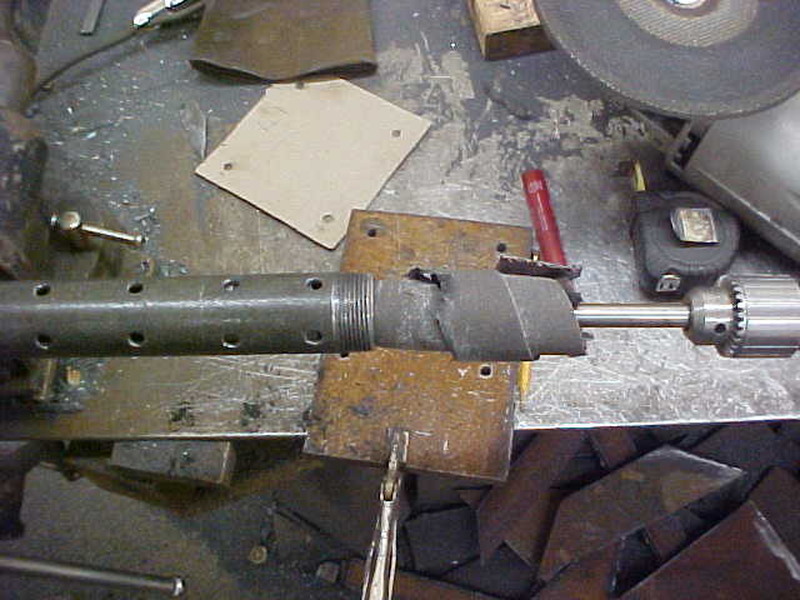
I just drilled holes in it to spread the fluid out and so there is no pressure buildup.
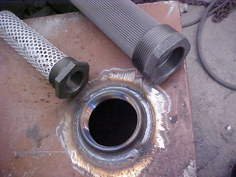
Weldable bungs make enlarging holes for bigger pipe and strainers a breeze
93green12v
ArboristSite Operative
Speaking of strainers, I have read some people don't run one and some people do. Honestly what are they going to strain from the pump? Do I have to worry about mill scale coming off over the years in this tank? I'm thinking it's going to be fine I just need to wire wheel the inside welds to remove any bits of wire and junk. Recommendations on pressure testing the tank once I weld the top? Saw that someone recommend shop air to pressurize and go around with soap and water to find bubbles.If it better for the design you can run a pipe diffuser with most of the holes on the opposite side.
I just drilled holes in it to spread the fluid out and so there is no pressure buildup.
Weldable bungs make enlarging holes for bigger pipe and strainers a breeze
When testing with air be very careful rectangular and tanks become round quickly with even low pressures.
93green12v
ArboristSite Operative
Any better way to test for leaks? Just fill it up and see what happens? I'm pretty confident it won't leak but I'll feel a lot better filling it with something other than expensive oil.When testing with air be very careful rectangular and tanks become round quickly with even low pressures.
93green12v
ArboristSite Operative
This is the idea I was going with or I'll get 1" bar stock. The bolts will go thru the sides instead of the top.Your ram is made differently than the OP. I agree with how you did yours and made mine the same way but the OP design will put the force sideways on the bolts - possibly breaking them off and binding in the 3/4" stock. Unless I misunderstood the OP, he cannot set his up like yours with the current ram design.
Attachments


="93green12v, post: 5605067, member: 138920"]QUOTE="muddstopper, post: 5604965, member: 73717"]You can put as many baffles as you want too. One is all that is needed. With a small tank and lots of oil flow, then you might need more baffles to break up turbulence.
You can mount your return filter anywhere you want to, but oil from filter to tank must be below the oil fill level. If yo wnat to mount your filter high or on top of the tank, just plumb the return line somwhere below the oil level, or run a pipe inside the tank to below the oil level. If oil drain back is an issue, then install a ball valve between the tank and the filter.
just pushed and pulled thru the pump. Returning oil thru the top of the tank is perfectly acceptable as long as the oil is piped below the oil fill level. One baffle is all that is really needed. A baffle with each bottom corner cut out will work just fine, but you do not want to use a baffle that is completely open across the bottom. Baffle shouldnt reach all the way to the top of the tank as this could create a vacuum on the suction side of the tank. Returning oil can create pressure inside the tank. A small amount of pressure inside the tank is acceptable. Vacuum inside a tank is not.[/QUOTE]
I was thinking of running two at 12" apart so I can make the oil travel some. What's an acceptable length of a baffle from the end of baffle to walk of tank?
What height would you recommend for the return if I run it thru the side and close to the bottom of the take? An 1" or 2"? The suction line should be at least 2" from the bottom so it doesn't suck up trash?[/QUOTE]
the purpose of the baffle is to let the oil settle out. Oil under pressure will trap air as well as other contaminates and is also carrying heat. The baffle separates the oil giving it time to settle down, let the air flow out, and transfer some of the heat. The baffle should extend side to side across the tank. Baffle height should be below the full level of the tank so that oil can travel over the top of the baffle. Bottom of baffle can have opening, but not completely bridge the bottom of the tank. A baffle made to create a full bridge across the bottom of the tank just pulls the oil straight from the return and under the baffle, along with all the nasties it might be carrying. Placing the return portat or almost at the bottom will cause the returning oil to wash up any nasties that might have accumalated at the bottom of the tank..I would keep the return at least a couple of inches off the bottom. A diffuser that divertes the returning oil side to side instead of directing flow downward is a good ideal, even tho lots of tanks dont use diffusers. . I also agree with using a suction strainer to help protect the pump. Even tho a good return filter will catch any small nasties, Bigger things often get into the tank, because of a plugged return filter, or carelessness when adding oil.
Similar threads
- Replies
- 6
- Views
- 750
- Replies
- 33
- Views
- 4K
- Replies
- 17
- Views
- 2K
- Replies
- 0
- Views
- 128