Husqvarna 55 Rancher Open Port Porting Job

Arborist Forum

Help Support Arborist Forum:

This site may earn a commission from merchant affiliate links, including eBay, Amazon, and others.
Joined
Dec 30, 2014
Messages
123
Reaction score
148
Location
Newbury, MA
So, I've got everything together, and I'm tearing into my Husky 55. I got the cylinder off today and everything looks brand new. Not many hours on the saw. I measured squish beforehand at .044", and the base gasket is .010". I plan to delete the base gasket and reassemble with something like Yamabond (OK, I don't have EVERYTHING together...). If I have this correct, the following will happen when I drop the cylinder .010"
1) The rising piston skirt will open the intake sooner. Can't fix that...
2) The falling piston skirt will close the intake later. I can raise the roof of the intake .010" to compensate.
3) The falling piston dome will open the exhaust port later. I can raise the roof of the exhaust .010" to compensate.
4) The falling piston dome will close the exhaust later. Can't fix that, either.
So, if that is correct, I will plan on widening the ports to 65% of piston skirt width, or to material limits, whichever comes first. I will raise the tops of the ports .010" to compensate for base gasket delete. I will make the sides of the ports relatively straight. I am confused by some of the nomenclature relative to "roofs" and "floors" of the intake and exhaust port. I want to think that the roof is nearest the top of the cylinder and the floor is near the bottom. But looking at pictures and comments on other posts (Brad's "Porting the 361 Big Bore", for example), I get the impression that the roof is where the port opens and the floor is where it closes. I notice from pictures that it is typically the bottom of the intake that gets the larger arc shape and the top that is flat. And for the exhaust, it appears the top is radiused and bottom is flat (Brad says, "Make the roof of the exhaust and floor of the intake "flattish",but make sure there's a slight radius so that the ring is tucked back in gently and doesn't snag.... The port should close from the sides to the center. The floor of the exhaust and roof of the intake are not that critical since that's not where flow initiates"). So, the intake port closes as the piston skirt falls past it on the down stroke, so the bottom gets the larger radius. And the exhaust port closes as the piston dome rises past it on the up stroke, so the top gets the larger radius. Is that right? But the opposing sides need a slight, but smaller radius, also - but flatter? The slight radius to be sure the rings are tucked back in nicely?
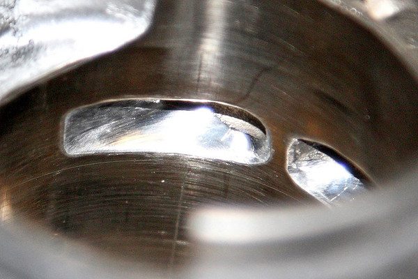
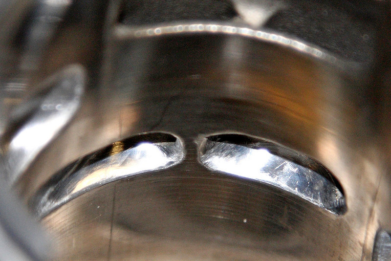
Thanks, I appreciate the help in advance - I will post pics next.
 
IMG_2249.jpg
Bits I will use. Will rough out with the carbides, then smooth with the sanding drum. Do these look okay?IMG_2242.jpg
Transfer port. Intake on left, exhaust on right.
IMG_2243.jpg
Other transfer port. Both are angled towards the intake.
IMG_2244.jpg
Ring locating pin. It is in center of intake port side, but piston doesn't drop that far so pin sees the port.
IMG_2245.jpg
Exhuast port. Appears to be some room to grind here.
IMG_2246.jpg
Intake port. Not so much room to grind here. Maybe more towards the inside of cylinder?
IMG_2247.jpg
Better shot of intake port.
IMG_2248.jpg
Another shot of exhaust port.

I am assuming that to grind these ports, I will do so from the outside of the port, using my dremel? I will not be able do much from the inside of the cylinder with that tool. I can bevel the ports using something (?) from the insides, though. They don't appear to be beveled much as is.

I printed out a degree wheel so I still may measure the port timing for fun/practice/learning - maybe with and without the base gasket, if I get it figured out. I guess I would do this by removing the clutch?
 

Attachments

  • IMG_2241.jpg
    IMG_2241.jpg
    74.5 KB · Views: 47
Oops, looking back at my post, I noticed I used roof wrong. Here is corrected text...
f I have this correct, the following will happen when I drop the cylinder .010"
1) The rising piston skirt will open the intake sooner. Can't fix that...
2) The falling piston skirt will close the intake later. I can raise the TOP of the intake .010" to compensate. (top is floor, right?)
3) The falling piston dome will open the exhaust port later. I can raise the TOP of the exhaust .010" to compensate. (top is roof, right?)
4) The falling piston dome will close the exhaust later. Can't fix that, either.
 
intake-aftero.jpg exhaust-aftera.jpg exhaust-afterb.jpg exhaust-aftero.jpg intake-aftera.jpg intake-afterb.jpg Well, I finished up Phase 1 of my porting job - so far so good. Mostly just widening so far - pics show befores (prior posts) and afters (above). Any comments? I have bought a clutch center piece and an aluminum degree wheel - need to figure out how to get that mounted up so I can get some timing numbers, to see if there is more to be done. May have to put it back together to see what it runs like so far... I bought some Permatex 80017 Aviation Form-A-Gasket sealer for the base gasket replacement. If I use this to put it back together to run it, will it be difficult to clean up afterwards when I go to measure the timing? How do you clean up the surfaces after you use this stuff? Any cleaning recommendations? I'd appreciate any comments on the quality of my work so far. The bits I used worked very well. The beveling was difficult to do, and seemed to be the operation that would be easiest to screw up the cylinder. I have read that a round abrasive bit is the best way to go about this? What diameter bit do folks use for the beveling. Thanks, Peter
 
Your porting looks nice. You will need to chamfer the ports. Put the wheel on and look for yourself but. I think you will find the transfers need to be raised. And the intake and exhaust re fine whee they are. Take the cage out of the muffler and. Then look at smoothing out the carb.
 
Thanks, David! I have chamfered ports - guess these were taken before I did that. Will get some updated ones posted when I get the wheel set up. I haven't found any pictures of ground transfers on a 55 - they all seem to get deleted after a while... If anyone has some I would love to see them. Seems like a tricky job with my Dremel, but I might be up for giving it a try. Will get timing numbers first!
 
The clutch nut gadget arrived, and I got the wheel, too. Need to weld an extension on to that, so I need to get over to a friend's shop to do the welding. You don't have any photos of raised transfers, do you? I'm thinking of taping some aluminum roof flashing inside the cylinder to protect the bore while I'm going at it. The edges are hard to do, to keep the bit only in the ports where you need it. Same trouble I have with the beveling!
 
Thanks, David! I have chamfered ports - guess these were taken before I did that. Will get some updated ones posted when I get the wheel set up. I haven't found any pictures of ground transfers on a 55 - they all seem to get deleted after a while... If anyone has some I would love to see them. Seems like a tricky job with my Dremel, but I might be up for giving it a try. Will get timing numbers first!

This is all I have hpe it helps some.
Shep 55 OP.jpg 55 OP Transfer.jpg
 
Shep,

Wow. You hogged the hell outta that sucker. Piston, too, I see. So, that piston work doesn't change the intake port timing at all, so the intake port is still shut at the bottom of the stroke and compressing the case and pushing fuel out the transfers (since the piston skirt was not changed in the vicinity of the intake port, just in the vicinity of the transfers). What that skirt work in the transfer area does is really open up the flow into the combustion chamber through the transfers, correct? The piston skirt work you did does not alter any of the timing at all, right? But you did raise the top of the transfer port in the cylinder, which will alter that timing. In the top picture, it appears you cut out the chamfered angles in the transfer ports (bottom of picture) that direct the fuel towards the intake, is that correct? Is that advisable? I guess the big question is, how does she run!?!?! Any photos of your intake and exhaust work? Thanks for digging these up and commenting on this post. I appreciate the help.
 
Ok, so I putit back together for a run before the timing, and it's leaking bar oil like crazy. Put clutch and bar on and off a few times and it is still really dumping oil. only part of the oil pump assy I touched was the cover and that was just to clean it out. Any ideas? It runs great, but very leaky....
 
Problem solved on the leaking bar oil - I think it was that little black grommet under the sheet metal cover not situated correctly. Ran the saw some today - runs awesome and sounds good. Not sure how much better, but well enough to make me tear into the MS361, take the limiters out, mod the muffler and get that saw unplugged. Now THAT made a big difference. Stock I think that saw is pretty plugged up and unhappy. Not totally set on the tuning yet, but it revs and sounds so much better. Can't wait to get into some good wood and compare those two. Will definitely have to do some videos....
 
Welcome to the addiction.

You port work looks clean and nicely done. The transfers are really hard to get to without a 90* handpiece. You can try stacked cutoff wheels on your Dremel, with a lot of time and patience, it can work.

I use a ball shaped stone to bevel ports.
 
Nice job! I have tried several times to raise transfers on scrap cylinders with a Dremel and no right angle handpiece. The best I did was with a cut down cutoff wheel, but even that was not good enough for me to try on a good jug. I did not like the shape I got, and I still had a major problem keeping the ports symmetrical given the direction of rotation of the wheel, and how the forces from that effected the tool on each side. It is way to easy to slip and trash the jug, so I have just not modified them.

Having said that, I have some engines that run really well, especially since I don't raise the exhausts radically. Also, a bit more blowdown angle allows more time for the exhaust to leave the cylinder before the fresh charge comes in, more time for the case to pressurize before the transfers open, and higher velocity in the transfers.

Last, I have to point out that in spite of what I've read in books and advice given here, I have yet to see a factory beveled port on any of the small engines I've modified. Although some of the Poulans seemed to have a very shallow depression cast into the cylinder wall around the port. Some of them had edges sharp enough to cut, and that includes one engine I just did where the factory exhaust port was at 60% of the bore with a very flat top and bottom edge. I'm not saying it's a bad idea, just what I've observed. I suspect that port beveling in a manufacturing environment would be time consuming hand operation, and that beveled port edges cause less distinct port timing events.
 
These were fine with a flex shaft Dremel from Lowe's and a cutoff wheel.

IMG_1690-M.jpg


IMG_1687-L.jpg
 
Not my work. Just some pic's of work I found and saved in case I wanted to do one. Yes opens flow to transfers doesn't change timing. Raising top of transfers does change timing.
Shep
Shep,

Wow. You hogged the hell outta that sucker. Piston, too, I see. So, that piston work doesn't change the intake port timing at all, so the intake port is still shut at the bottom of the stroke and compressing the case and pushing fuel out the transfers (since the piston skirt was not changed in the vicinity of the intake port, just in the vicinity of the transfers). What that skirt work in the transfer area does is really open up the flow into the combustion chamber through the transfers, correct? The piston skirt work you did does not alter any of the timing at all, right? But you did raise the top of the transfer port in the cylinder, which will alter that timing. In the top picture, it appears you cut out the chamfered angles in the transfer ports (bottom of picture) that direct the fuel towards the intake, is that correct? Is that advisable? I guess the big question is, how does she run!?!?! Any photos of your intake and exhaust work? Thanks for digging these up and commenting on this post. I appreciate the help.
 
These were fine with a flex shaft Dremel from Lowe's and a cutoff wheel.

IMG_1690-M.jpg


IMG_1687-L.jpg
Nice job - I wasn't able to do nearly that well, but maybe the smaller end with the flex shaft helped. My "Dremel" is a HF knock off which works fine but is certainly not slim.
 
Back
Top