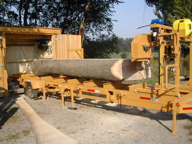
I see a lot of people that are building a mill opt to go with the 'V' of the angle pointing up for their track rails, and altho it seems to work and I know a lot of large manufacturers use this same method, I can't understand the reasoning for it. In contrast, I believe using the 'upright leg' method affords the advantage of a smaller area for sawdust to collect on the top of the track and get stuck to the wheel. It also provides a smaller surface area where a track wheel will ride, making for less friction & resistance, meaning it will be easier to push just by design.
I designed a set of wheels for my own mill that are giving me a great deal of success. These wheels are like a railroad car wheel in that they only have one flange, but the portion of the wheel that actually rides on the track rail is wide enough, (1-1/2"), that if your track isn't consistent in width, or your carriage frame flexes slightly, it won't fall off because that single flange catches the track rail before the other wheels run off the 1-1/2" flat surface area.
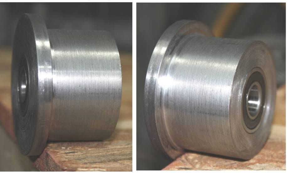
I reasoned that the problem with a 2 flange wheel is that a carriage is hardly ever pushed straight and square down the track. We are almost always pushing on one side of the carriage frame, which in effect, makes the carriage try and 'cock' on the track. Even when we push in the middle of the carriage, the pulling effect of the blade going thru the log is trying to pull the carriage off the track. When this happens, the same effect is happening to the track wheels, and both wheel flanges on each wheel are rubbing the sides of the track rail, one at the front of each wheel and one at the rear. This is what keeps the carriage from coming off the track, but it is also creating resistance, making the carriage harder to push. The same principle applies to the V-Groove wheels. I didn't realize just how much resistance was being created until my original track wheels self-destructed and I came up with this idea. With only one flange on each wheel, the resistance is literally cut in half. The mill rolls so much easier now I can move it with pressure from two fingers instead of having to 'lean into it'. And because there's only one flange, it doesn't matter what thickness the angle is either.
Most of us use 2" X 2" or 2" X 3" tubing for the bottom horizontal rails of our carriages. Because the wheels are 1 1/2" in width, they'll fit nicely inside a 2" square tube without having to make another 'wall' or a spacer to retain the wheel so it doesn't float back and forth. If you're using 1/4" walled square tube, you may have to grind the weld seam that is inside the tube if you place the seam on a side wall. This depends on the manufacturer of the tubing, as some weld seams don't protrude as much as others.
Here's a pic if any of you with a lathe wanna copy them;


 My job was mill welding maintenance and for the 8 years I was there, the only thing I ever did in regards to that whole set-up was replace bearings in the wheels. I agree that more surface area the inverted angle affords will spread weight out, but I don't think it will make for less rolling resistance.