RaisedByWolves
Addicted to ArboristSite
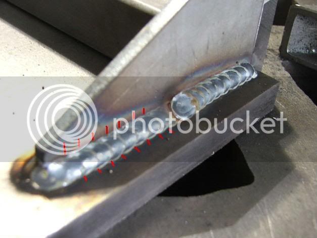
Yes, very hot indeed.
Whats that frame 1/4"? 3/16? Somewhere in between?
Over all looks very good, This is with your new unit?
Wheel or foot?
Whats that frame 1/4"? 3/16? Somewhere in between?
Over all looks very good, This is with your new unit?
Rspike said:rated at 3,000 lbs 4k max. Not that the trailer it self would ever need it but if it was filled with wood and need to be off the hitch then it comes into play.
Wheel or foot?
 What project is next?
")