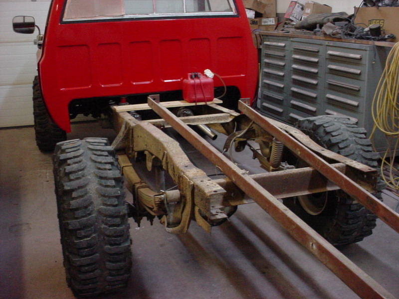
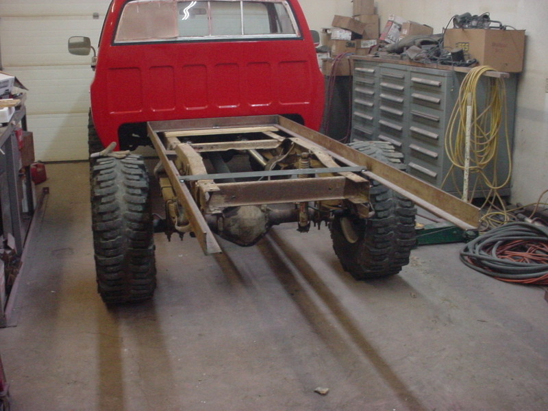
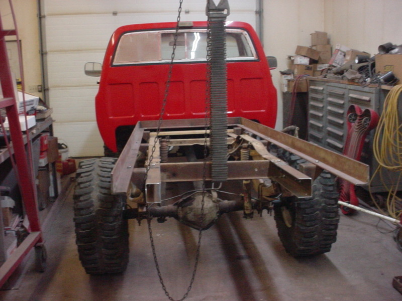
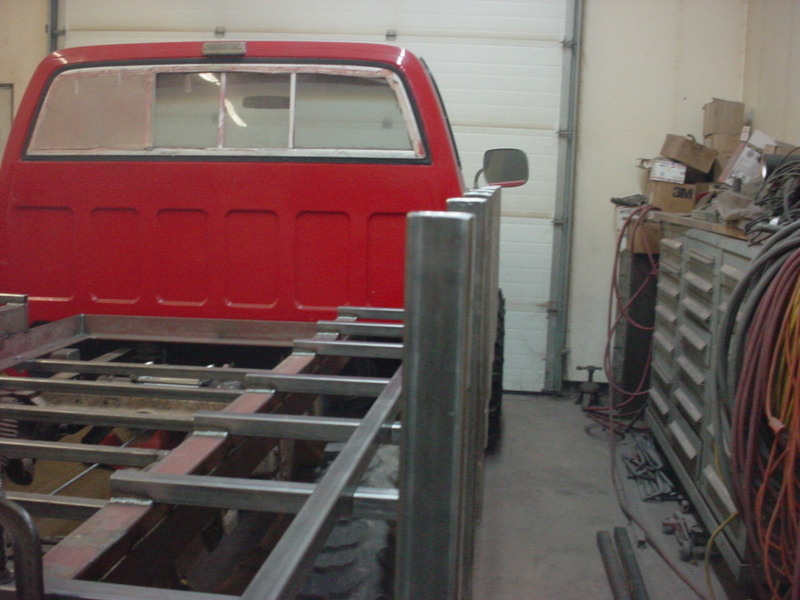
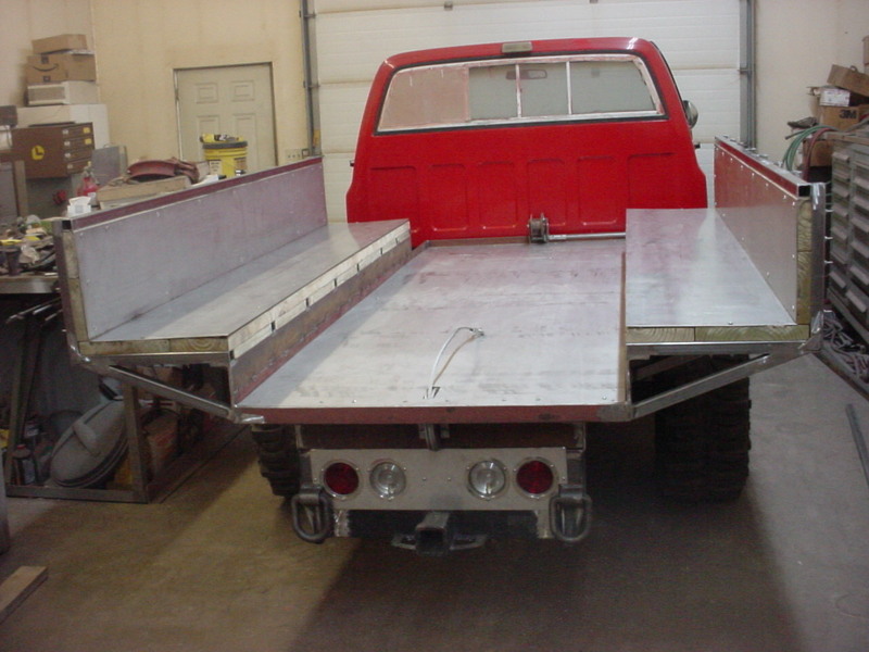
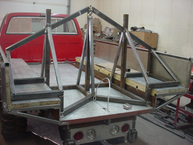
Been kicking ideas around in my head for years on what would work best for the process I use to haul wood. Been using a standard Chevy pickup and a 1/2 ton at that. LOL It has served me well but an upgrade was in order so I found a model I could work with with a soild base. A 1980 Chevy k30 dually. It was rough and needed a lot of body work and fixing. Most would have junked the cab but I used ir as a learning tool for metal work/replacement. I will give a link to the whole thing at the end of this so you can see the extent. I've never see what I came up with before so tag along for the build and we'll see if it works out. Again, Not saying this is the best/only way but it is what I feel will work the best for me.
I am using the worn tires from my show truck. They are 38x15x16.5 Swamper Boggers. Want some solid siderails for it so using 3/8" thick angle iron. For what I have planned, it will have some heavy weight and forces on it.
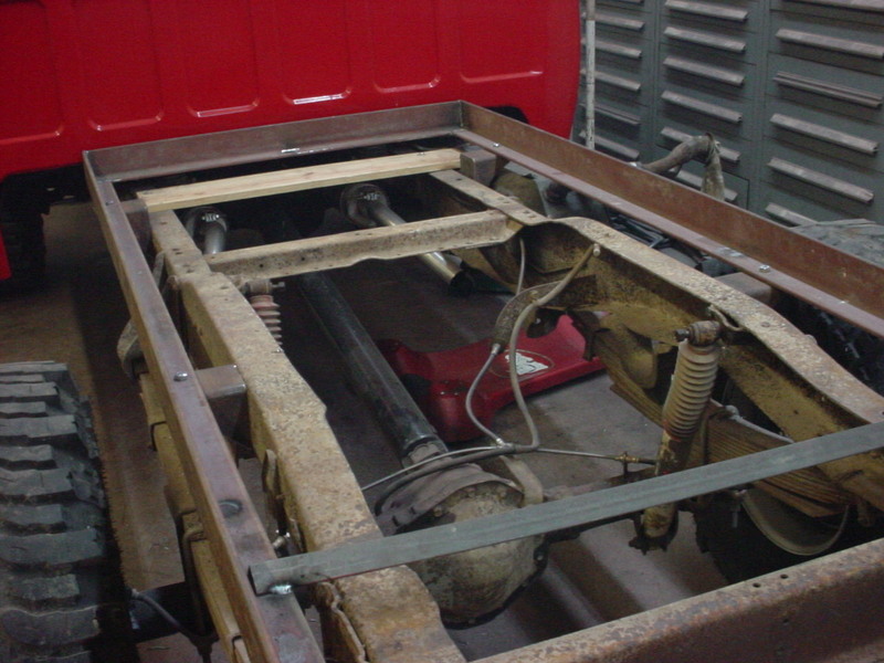
Doing some measuring and level finding so I have something to go off of.
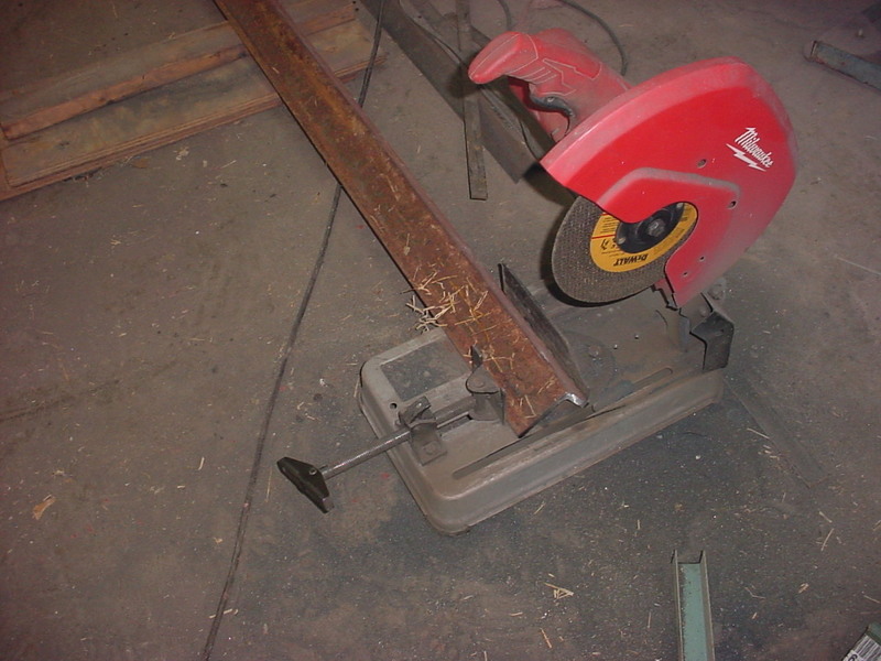
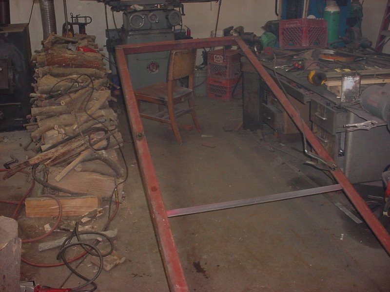
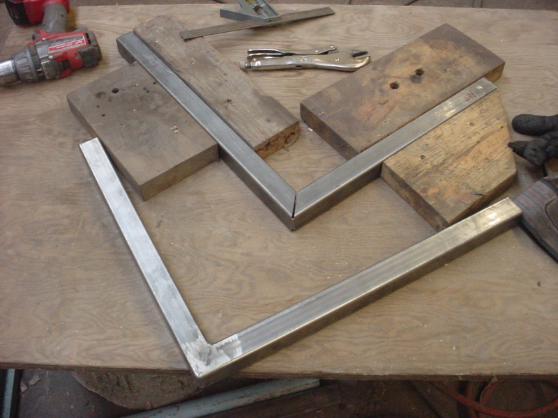
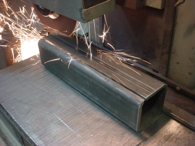
I decide on 44 inches wide and cut the length to 11 foot. I will have some dead space in the front but want 8 foot of flat floor. I went long on the side rails till I see what I have and will shorten them up when I get that figured out. Just using a chop saw to get nice cuts.
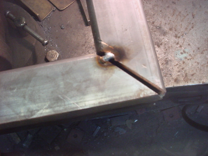
Final welded the front and inlaid another section of angle there. On the back, I just welded in a temporary piece of small angle. Measures it to ride on the frame so I can put spacers under it till I get my position where it needs to be.
I cut notches pluse releaved edges in the angle so it all lays flush and have more welded area.
With it laying on there I can make all the adjustments now by measuring side to side and such.
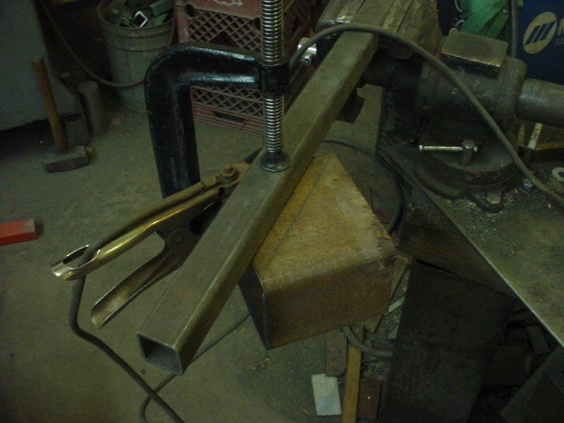
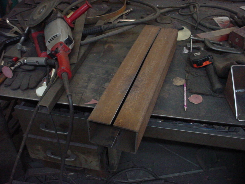
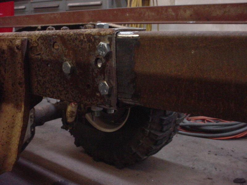
To mount it to the frame I'll make up 6 mounts to distribute the load. Going to use a 4 x 6 box beam and have about a 5 inch outward length.
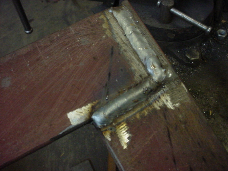
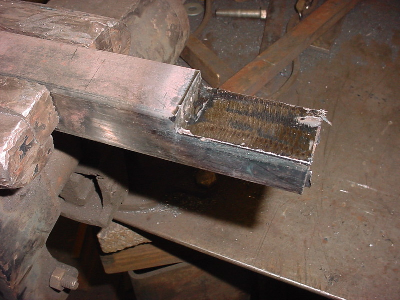
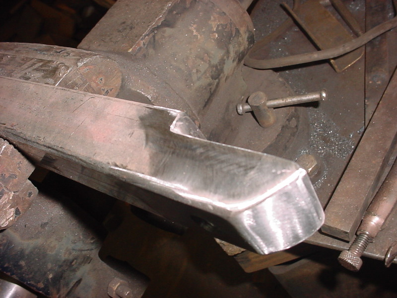
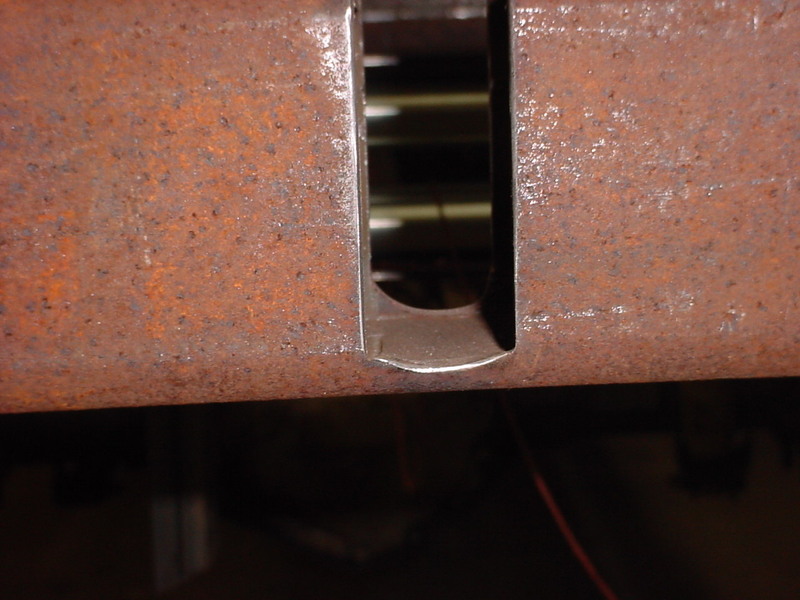
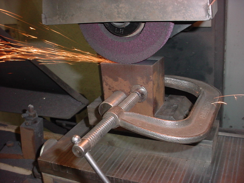
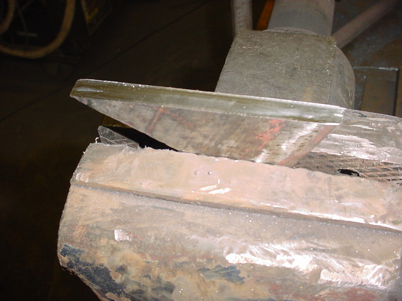
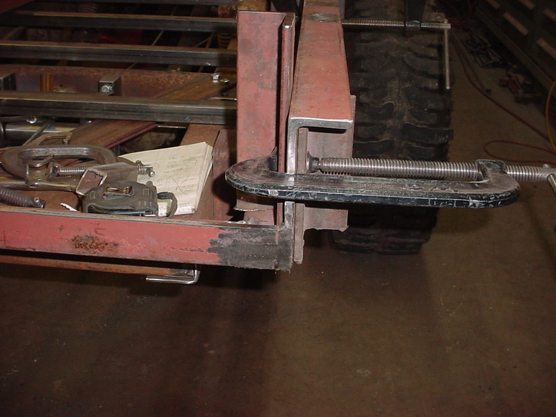
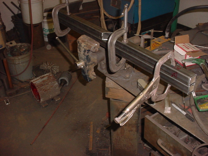
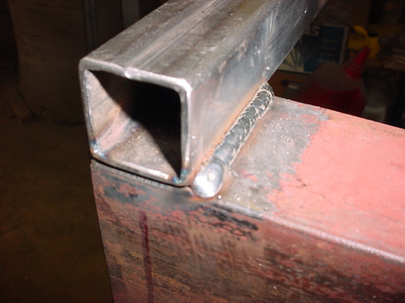
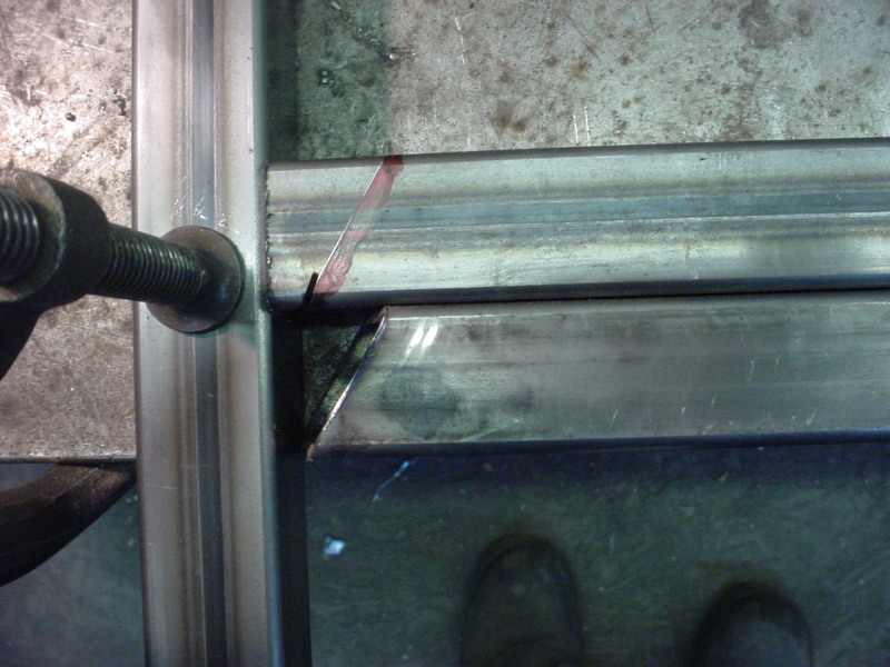
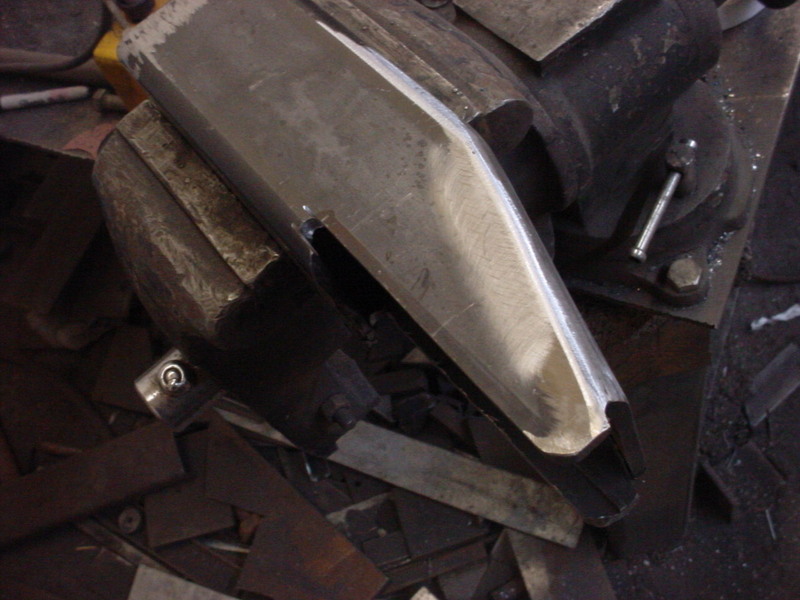
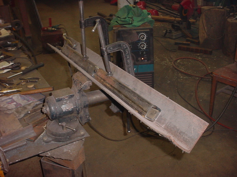
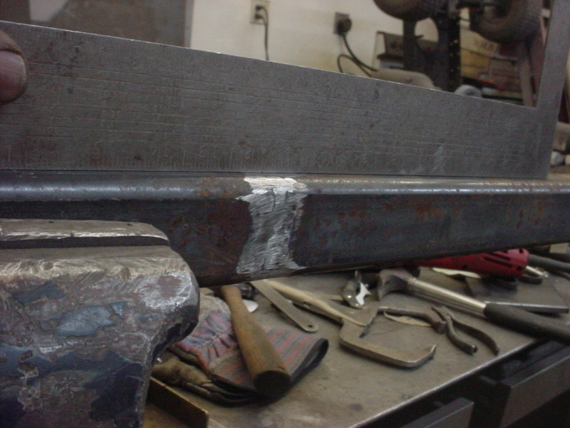
Handy hint when you have short stuff is to hold a straight edge (this case a piece of square tubing) in a vise and then clamp your piece to that.
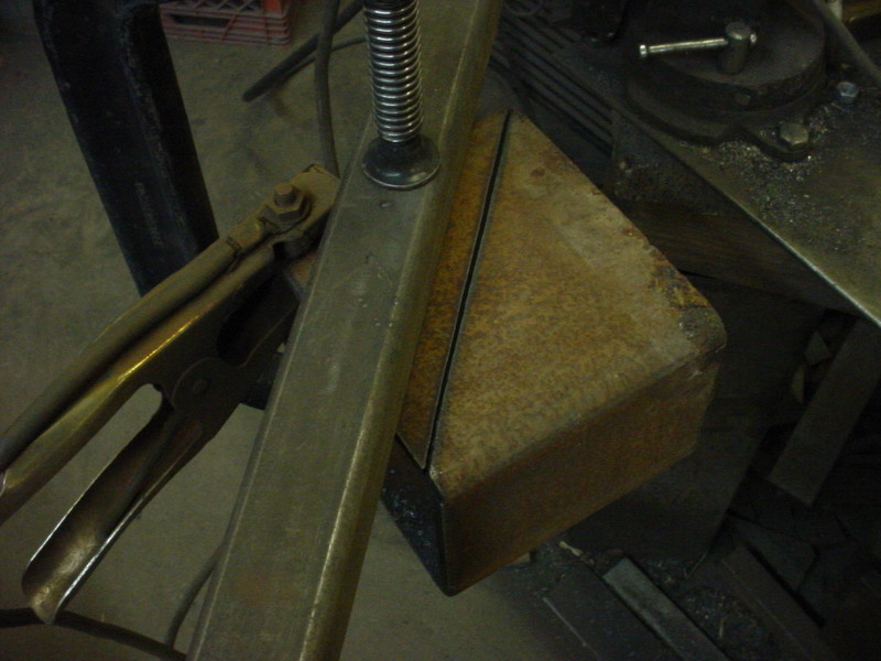
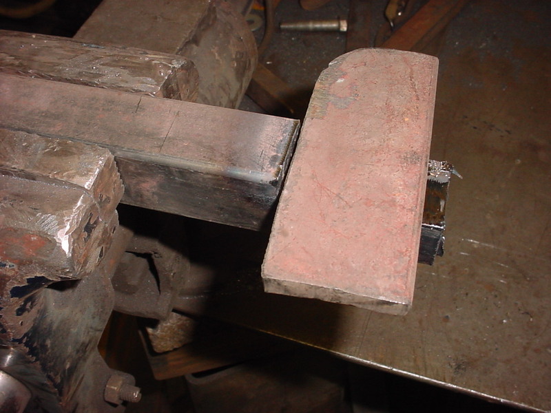
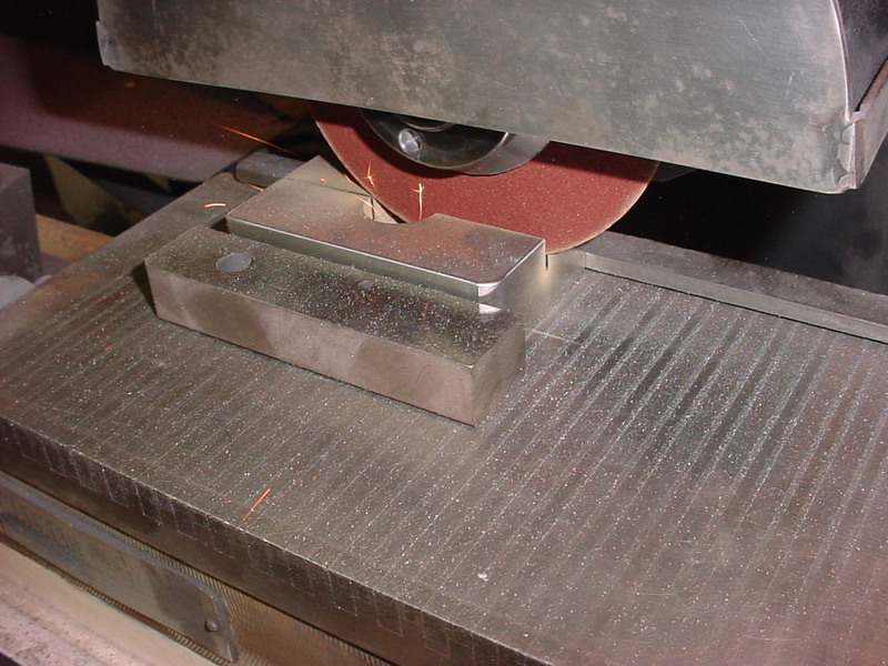
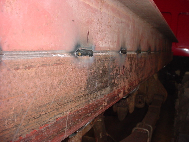
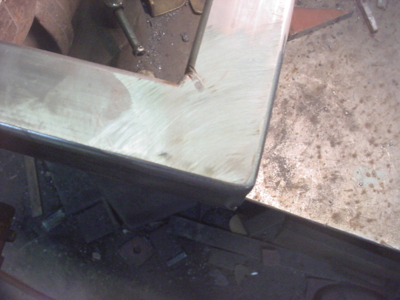
On the back side I ground a 45 about 1/2 was through the piece then welded it pretty much flush. then Ground it all smooth do it'll mount to the frame nice.
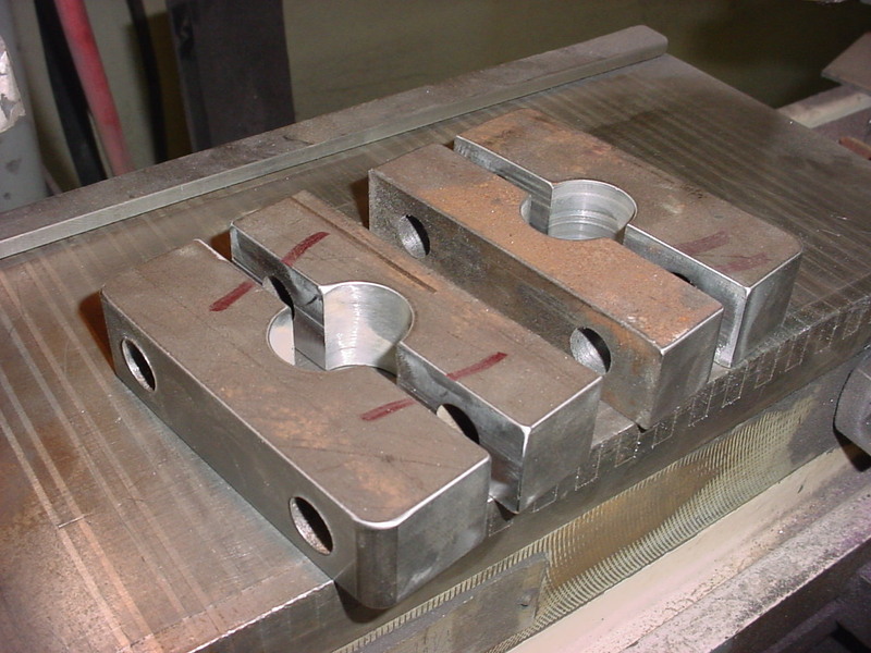
All 6 done now so I'll mount them up via 1/2" bolts one at a a time.
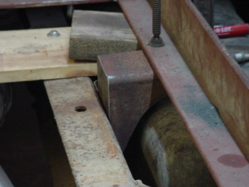
One mount was going to be where the fuel tank mounts. Decided to throw it back on to double check and did indeed have to trim one for clearence. I just clamp it and drill the hole and then install the bolt to hold. Then drill the rest and bolt till it's done. Kept checking to make sure it didn't move any side to side.
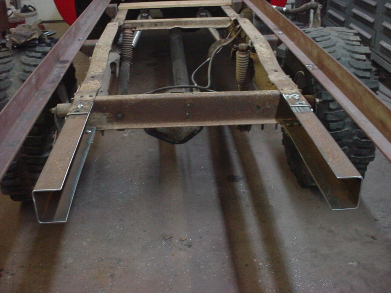
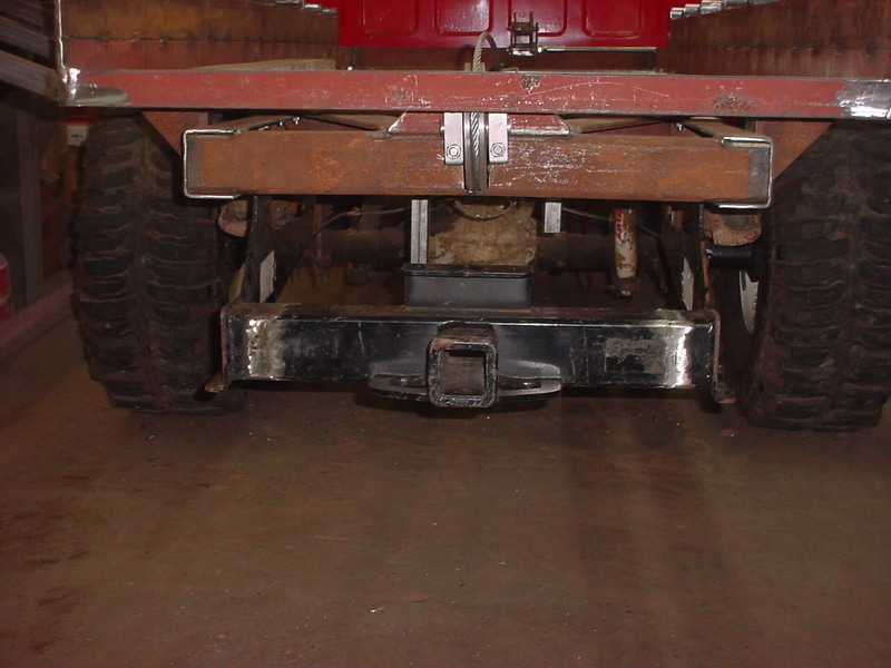
4 of 6 on and done. Going to extend the rear frame some next as that had to be there for the mount.
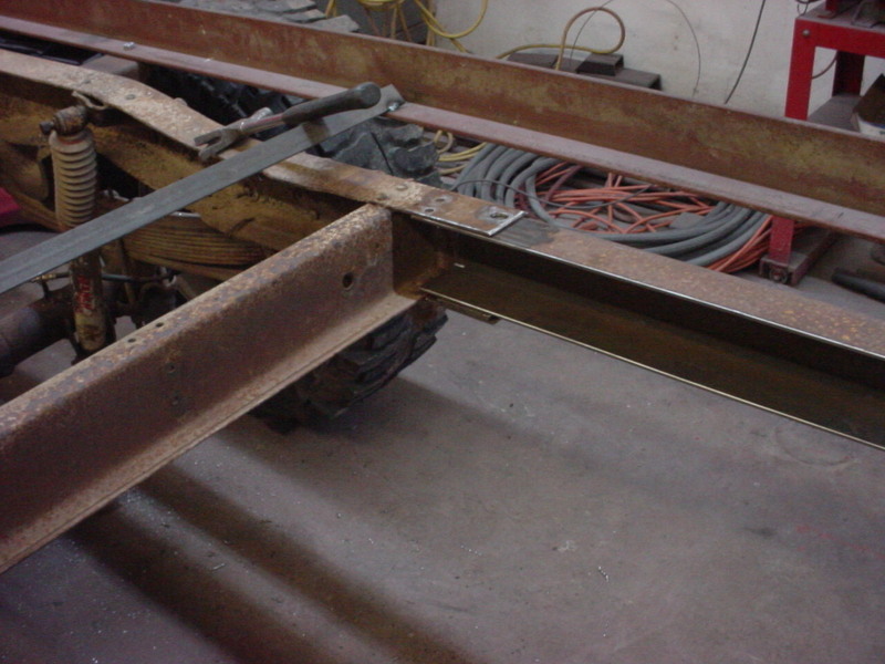
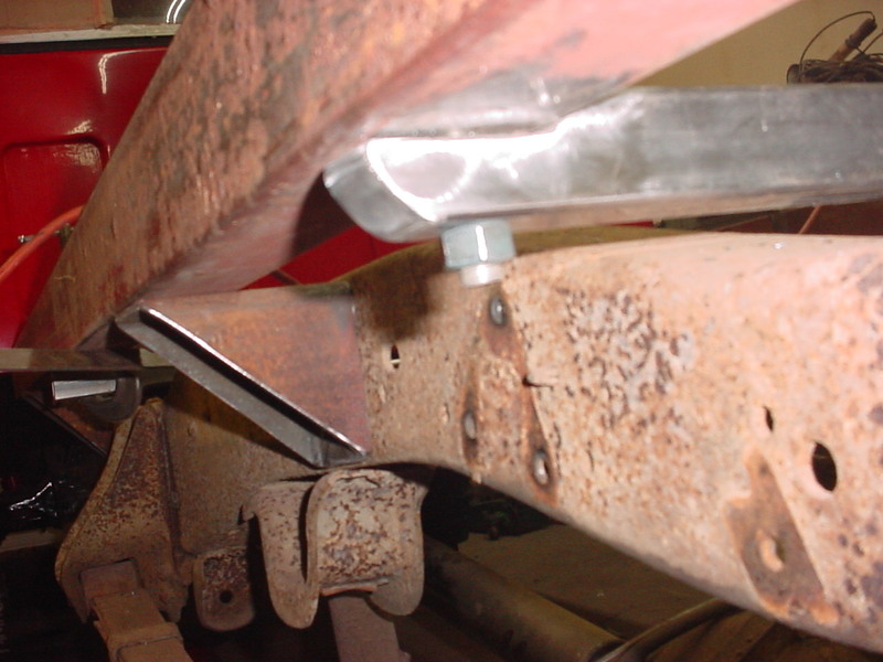
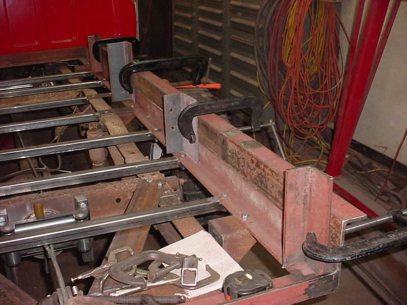
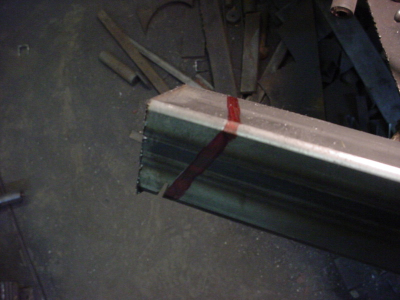
Did a alot of measuring and decided on what length I wanted for the frame and floor. I took the 4x6 box beam that was 3/16" thick and sliced it down the middle with the plasma cutter. Frame is an oddball size so I'll just slip this inside the C channel of it.
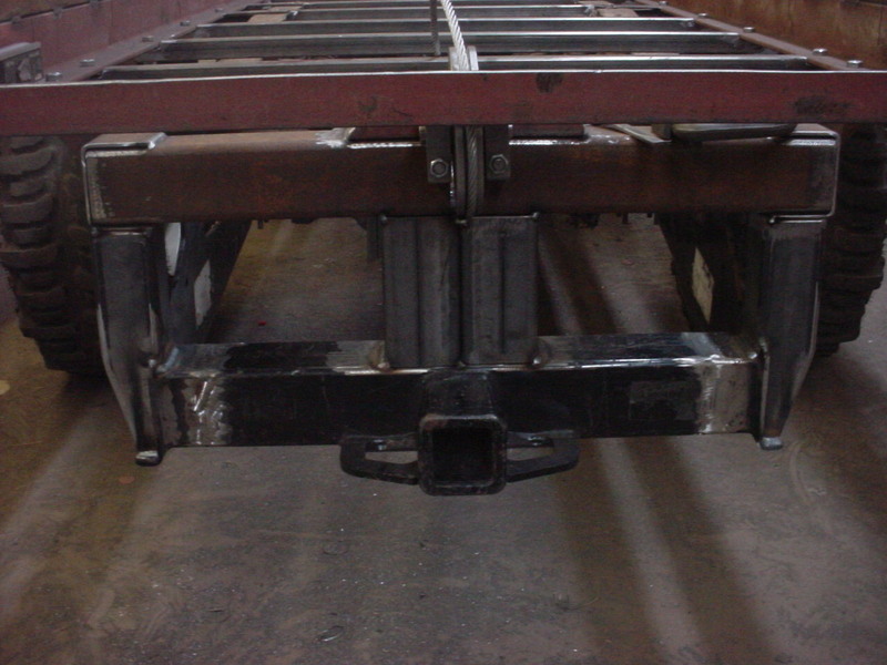
It fits tight with a spacer under the bottom. Actually drove that in there. When I did both side it pretty much self aligned both sides.
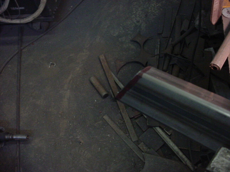
Ended up being an extra 2 ft.
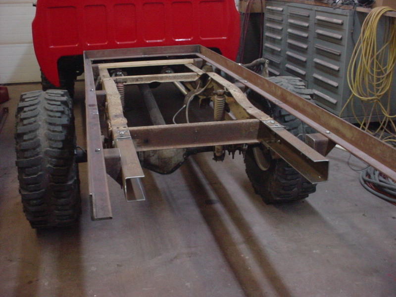
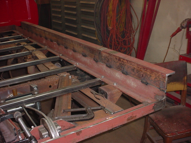
I'm using 6, 1/2" bolts. I was going to weld it all but once I saw how it drew it all in, it looks like that will be enough. The bed frame work and more crossmembers will add a lot of strength to it as well.
The bolts pulled it all straight again. I'll put the back bed mounts on next.
More measuring to make sure everything was in line and had to spread the rail just a little to insure the lip on the rail doesn't taper in. That will come into play with what I have planned.
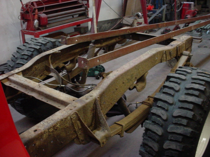
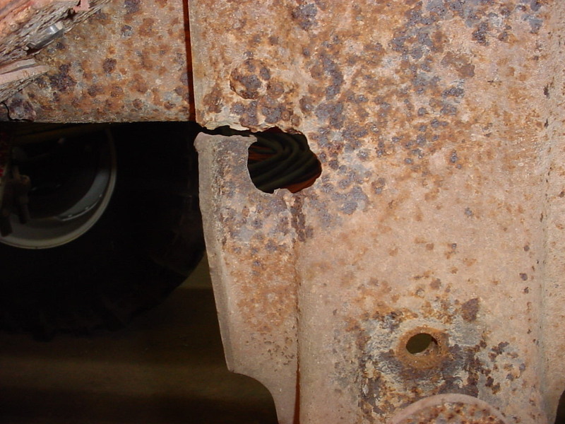
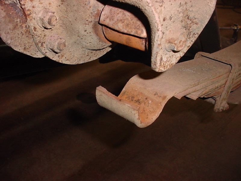
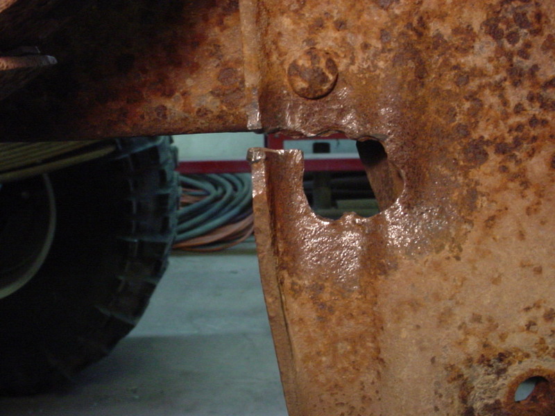
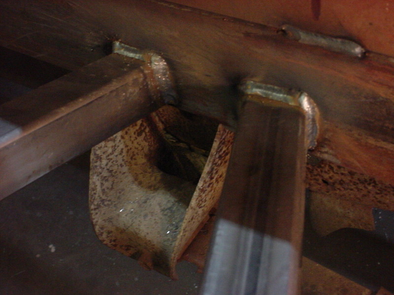
The truck has had some questionable repairs methods done to it and this is one of those. They replaced the rear shackles but to get the bolt out they decided to blow a hole in the spring hanger. That was bad enough but they cut through the edge as well and the whole hanger will flex. I'll repair this now.
To give myself some more room to work I'll lift the back of the truck up and take the shackle loose.
When I did that I got a surprise. The front spring eye on the top rear leaf was broke! It was just floating there and held in place by weight. One good bounce could be REAL ugly. I'll get some replacements for this.
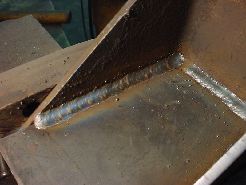
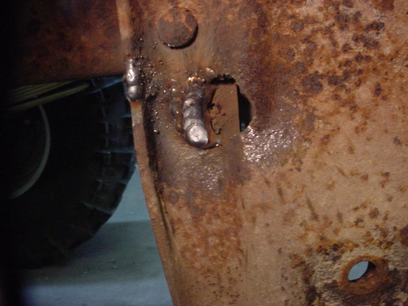
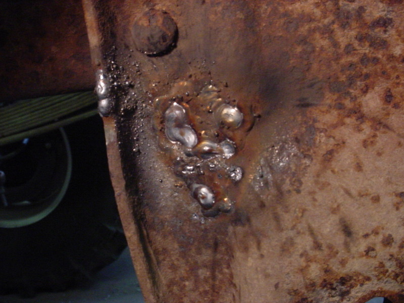
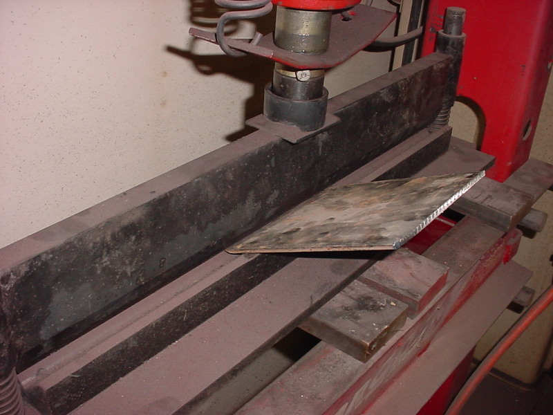
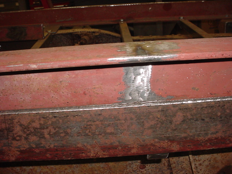
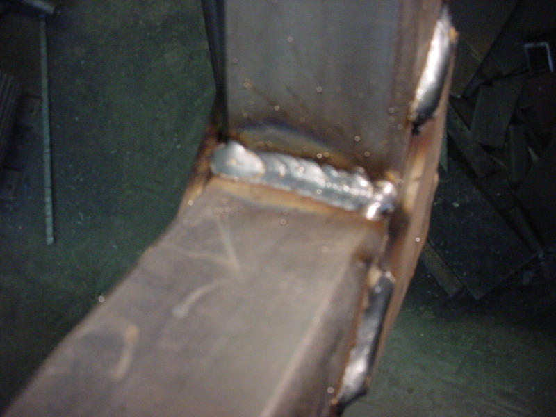
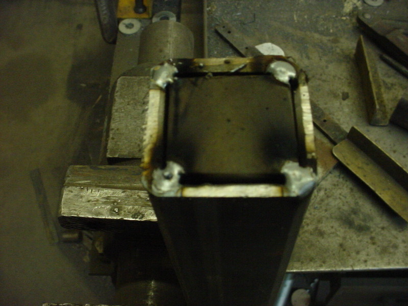
To start the repair I hit the whole area with a needle scaler. This gets into the nooks and crannies to remove rust and scale
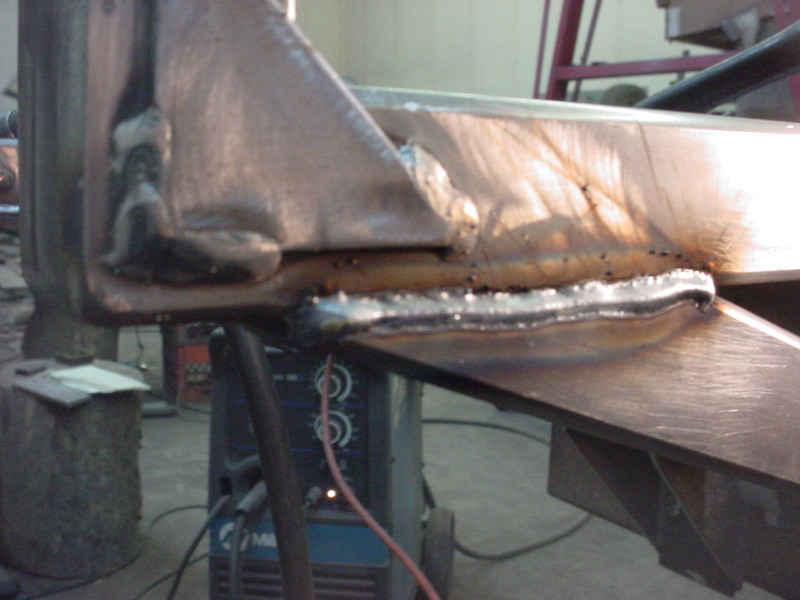
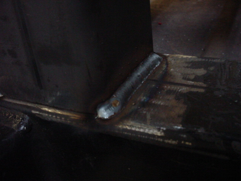
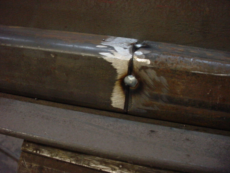
Then I start welding using a thick, copper backer. I turn the amps up as high as I can for max penetration. Shorter bursts and start filling.
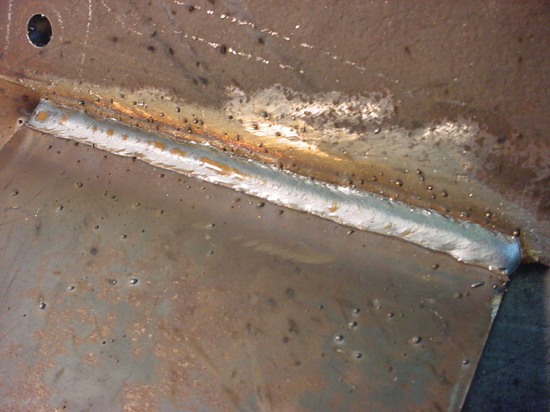
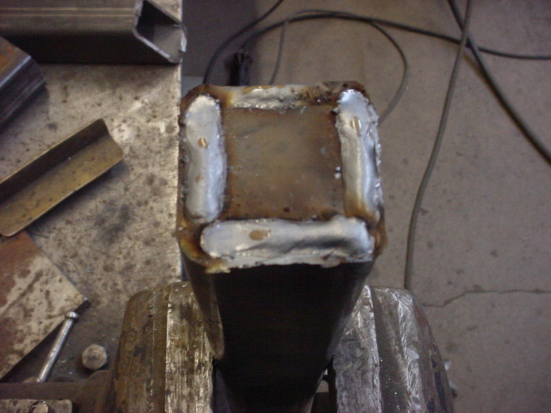
Keep going to it looks like there are no lows. The high extra will only mean more work for smoothing so it's a give and take.
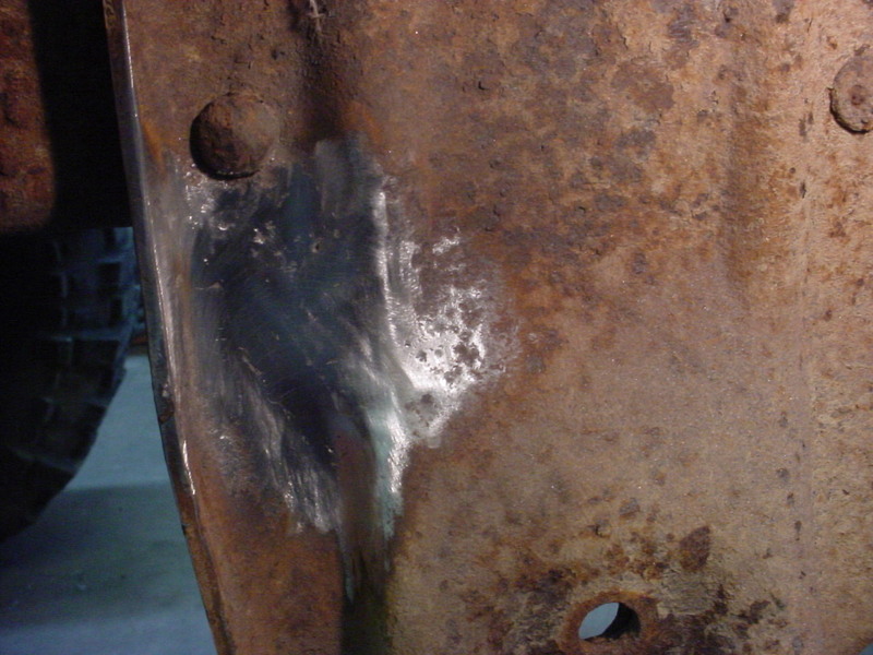
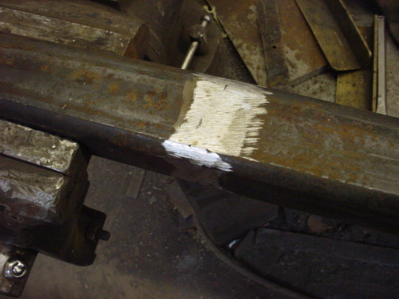
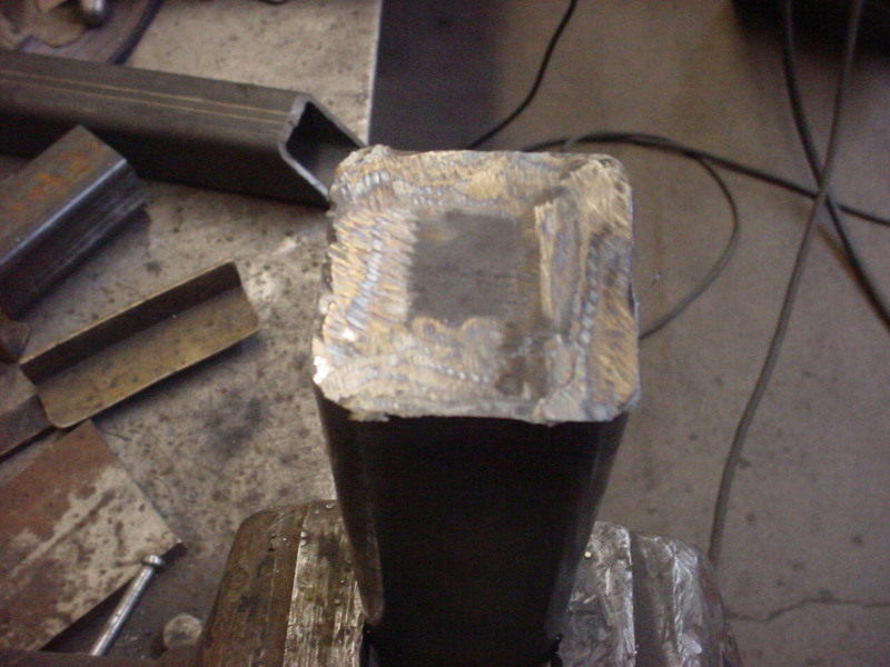
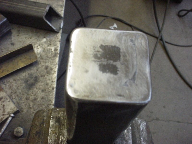
Small angle grinder, die grinder, Dynafile and a soft pad on a die grinder were used to bring it back down. There will be a lot less flexing now.
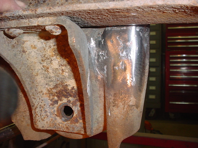
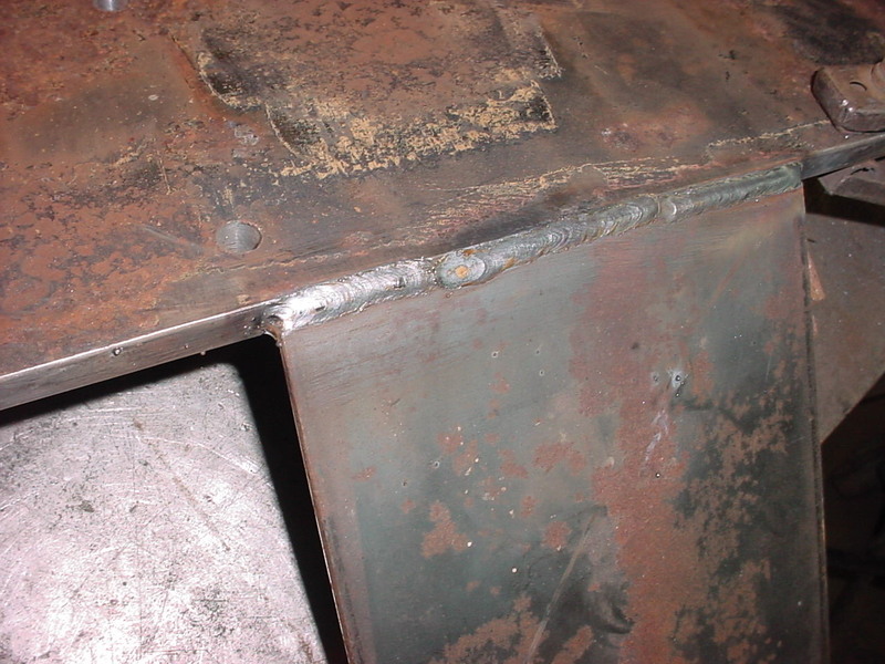
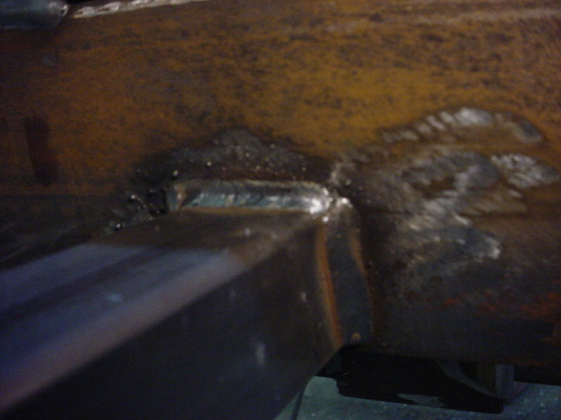
The back side of the repair
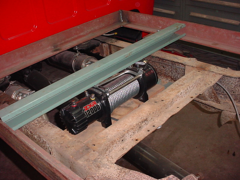
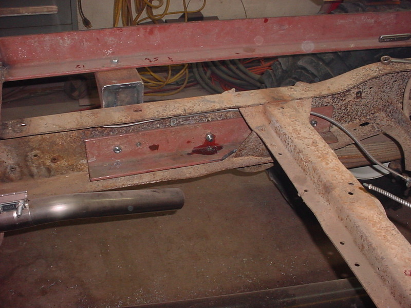
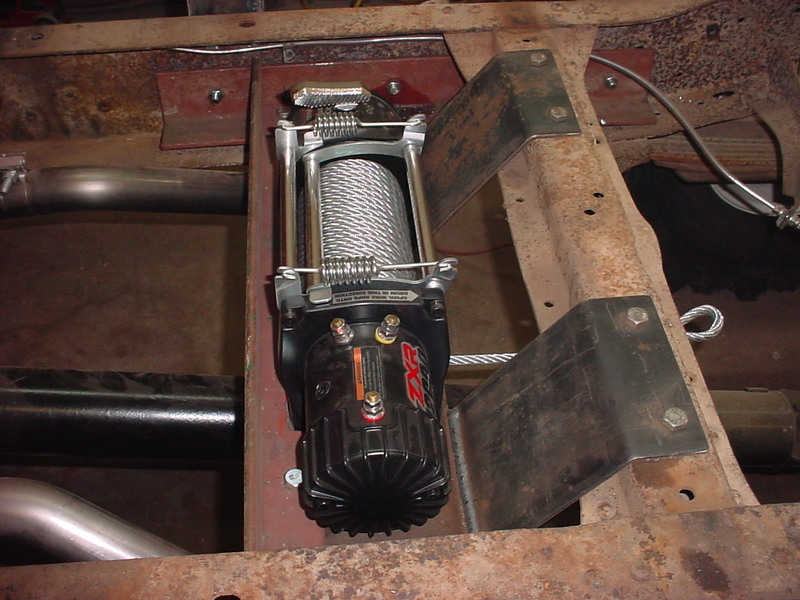
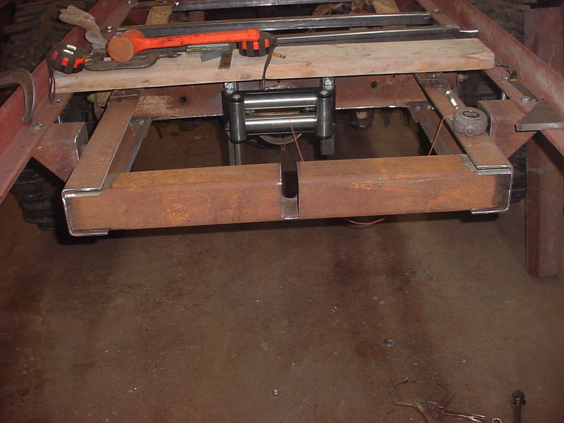
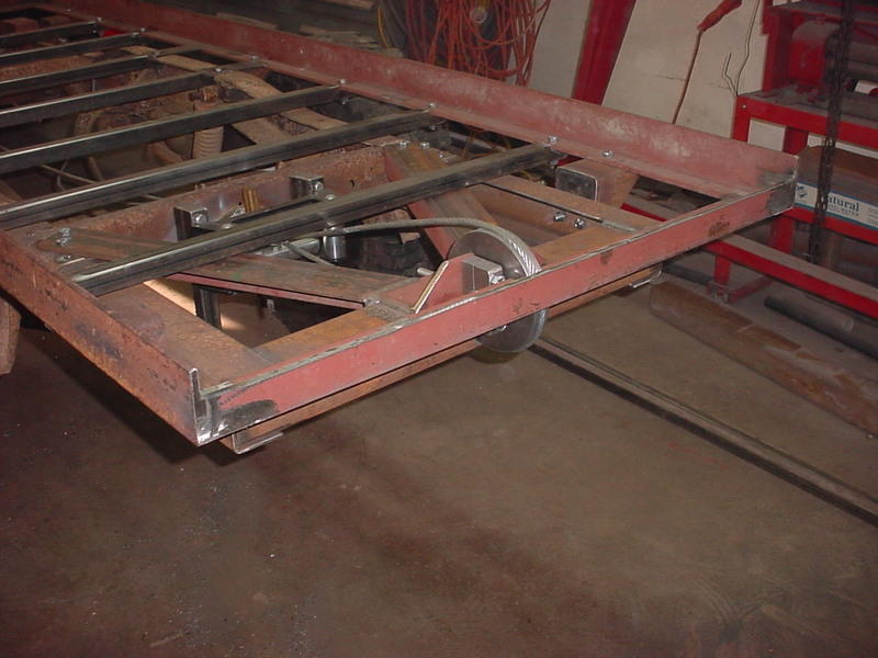
Next I'll mount the winch in the frame. Got a rail to show the underside of the floor so I know my clearance. I mocked up where it needs to be and scribed lines and wrote down measurements.
Used the same 3 x 4 x 3/8" angle iron for this. I avoided the frame rivets and also bridged the front rear spring hanger. If you break a frame, this is where it will happen. I used existing holes in the frame and just opened them up to accept 1/2" bolts. 5 bolts per side.
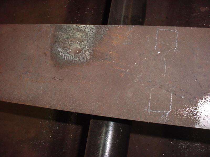
For a base I used a 1/2" thick plate. It's 7 x 32 inches. Have it where it needs to go so I'll drill the mounting holes next.
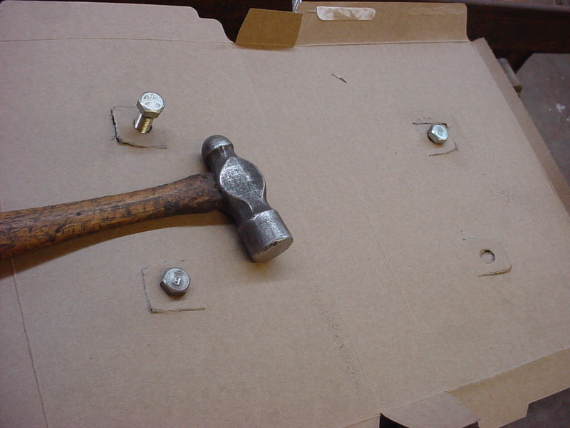
I keep it simple and use a ball peen hammer to make a pattern from a cereral box. Lightly tap the edges with the flat part of the hammer for the edges. The holes I use the ball end. Get it to this point then just use scissors to connect the edges.
I penciled around the same feet of the winch when I had it in place so I just lay the pattern on this and centerpunch the holes before drilling.
Now I'll make some reinforcements. Flat plate with a winch could bend. Decided on what I thought would help and bending some 3/16" plate here.
Did some fitting and tacked them on. Once it all checked out I final welded it. I had to have something that would be able to take on and off so the design has to take that in consideration.
Underside of the same plate.
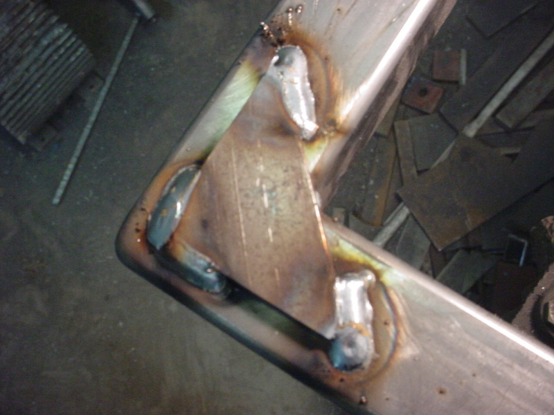
I used another piece of 3/8" angle on the other side. The force will be clockwise in the view so it would want to pull down on the right and lift on the left. The 2 plates on the crossmemberhave angle gussets coming up from the bottom of the frame. This should distribute the load.
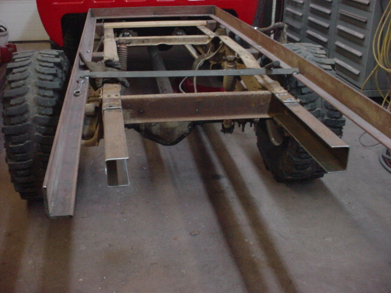
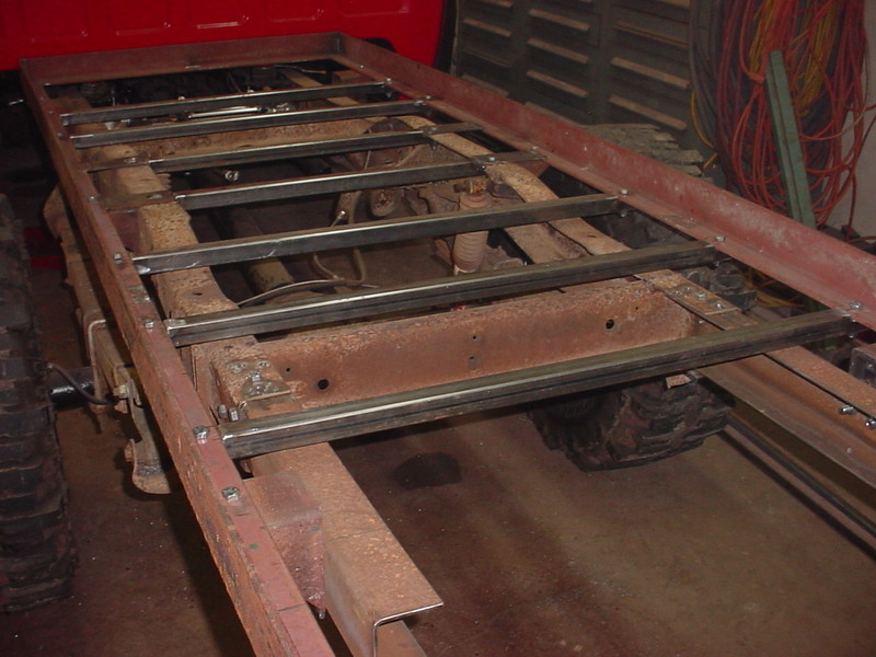
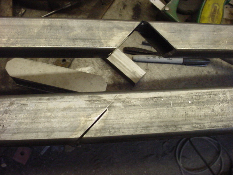
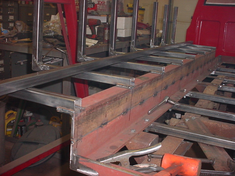
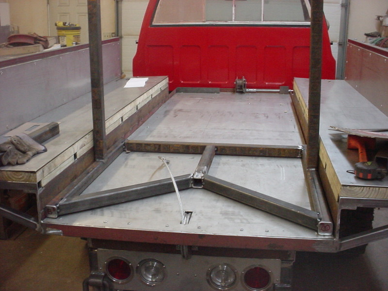
Next up is the floor crossmenbers. The angle will have the Pressure treated wood sitting in the rail so I'll have to notch the box tubing so it will lay flush and support. For postioning, I started with both sides of the axle kick up in the frame. Pushed them till it hit and when I notch the 3/8", it will be above the frame that much. I just marked the edges when I had it mocked up.
Used a cut off wheel and laid that metal back in and welded it. The gaps made it so I had a good weld.
I used a scrap piece of 3/8" to check it all was flush before welding. Then just ground it smooth.
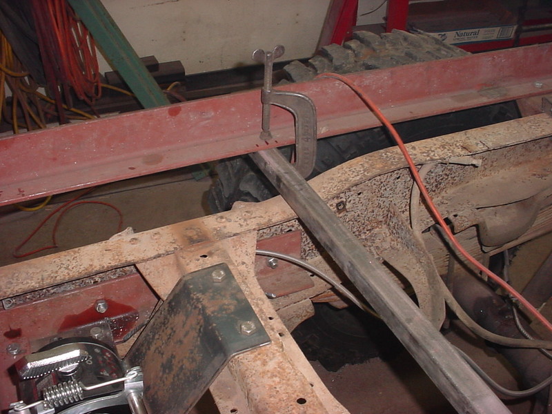
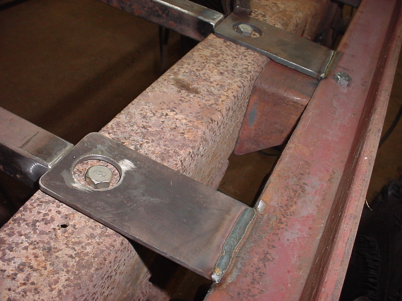
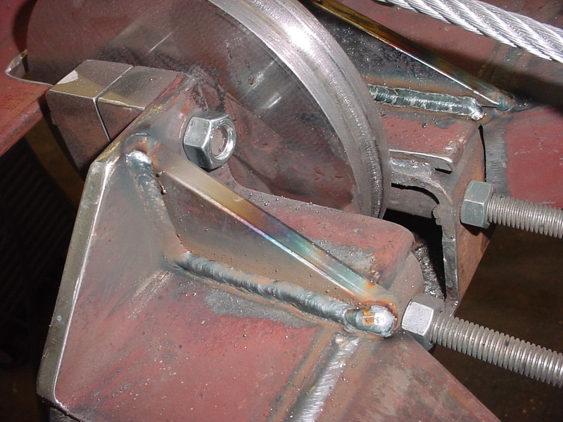
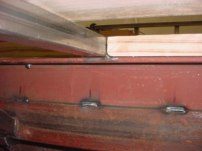
Put it back on the truck and drilled the holes while holding it place with C clamps. Figured I better put heavy pipe spacers inde the box because if you don't, The 1/2" bolts would crush the box tubing and become loose. I drive them in then tack weld in position.
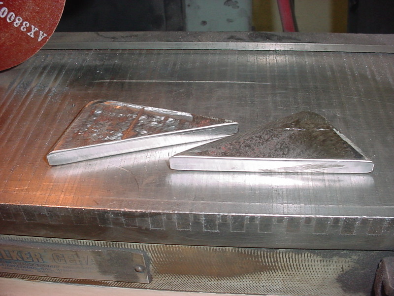
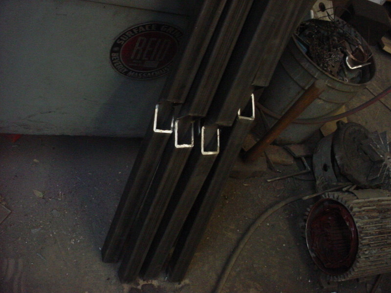
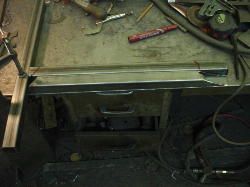
Decided to pretty up the ends instead of leaving the open box. I used the cut off wheel again and cut a triangle out of both sides. Then bent the lower edge up and welded it all. Ground it and then sanded smooth. No sharp edges to cut yourself on that way.
Got all the crossmambers for the floor made except the rear on which will be different. The 2 middle ones I had to mount them into the frame rails. I want the floor as low as possible so the hump in the frame is my limit.
Needed to support the pressure treated wood floor to those 2 middle crossmembers on the putside of the frame so I just welded spacers to the outside and will let them rest on the top of the frame.
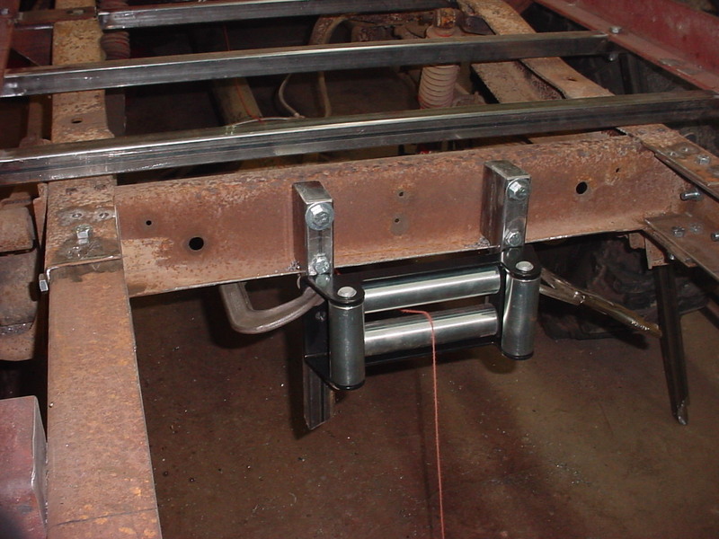
Made up some mounts for the roller fairlead. I will probably get some side bracing later as well as drilling the holes to mount it. I may need to adjust depending on the end crossmeber and pulley.
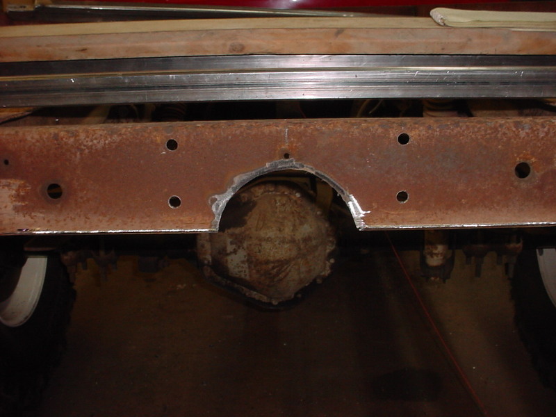
Looking at where the cable will be I decided to raise it up some. This meant the crossmember had to be relieved some. With suspension compression from weight I'd be close to hitting the Diff. if I didn't do this.
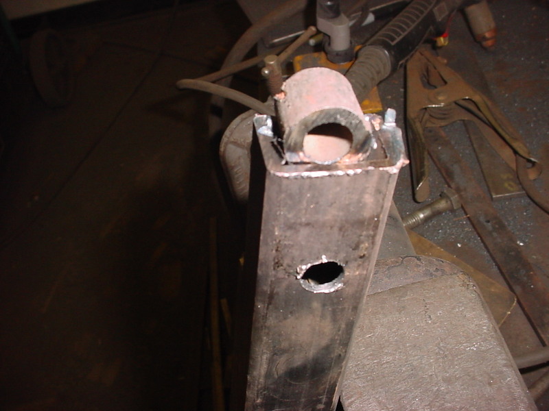
I just cut a piece of heavy wall pipe and traced a line. I'll weld this in.
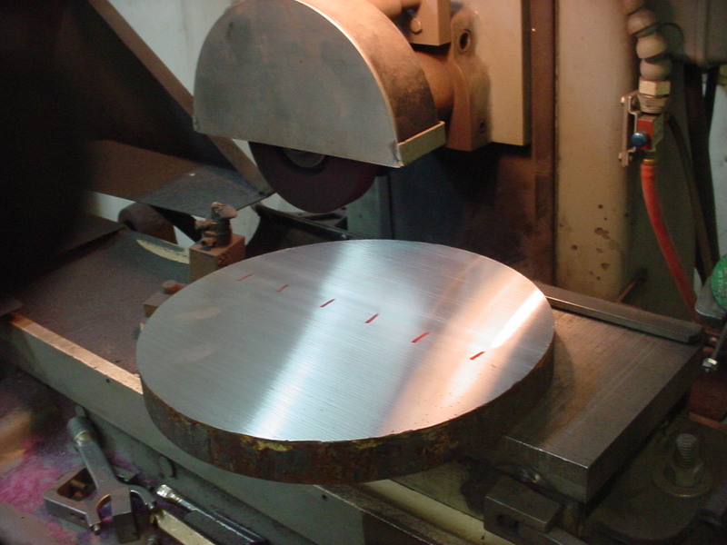
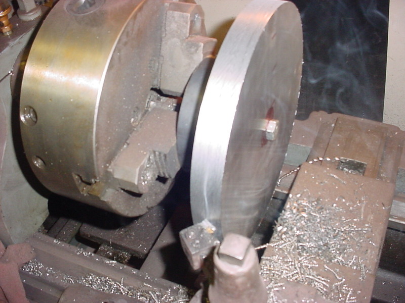
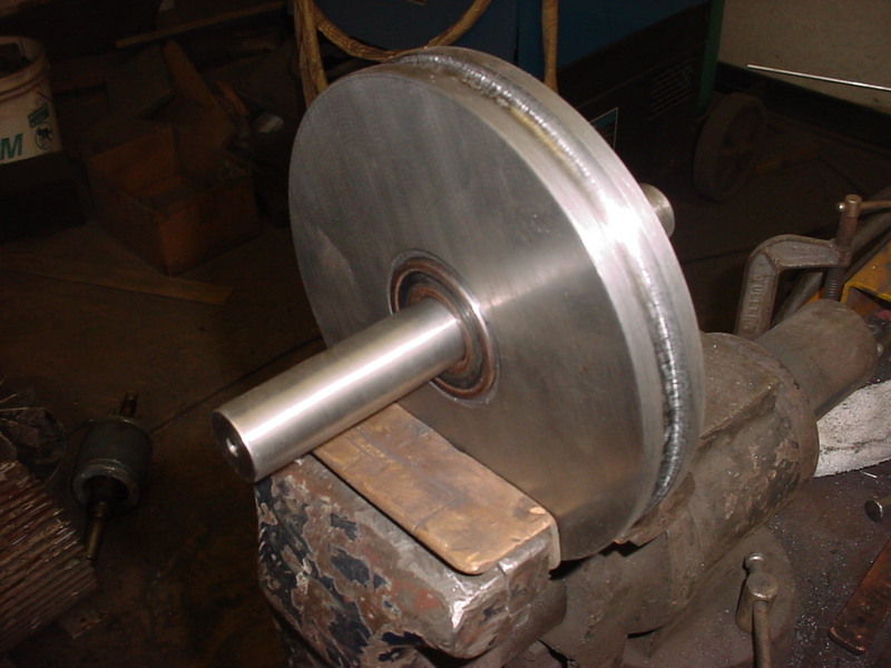
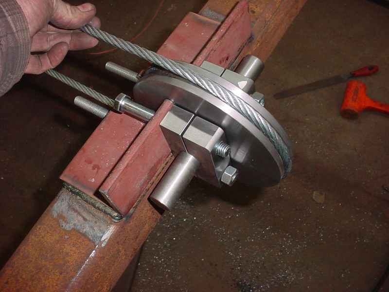
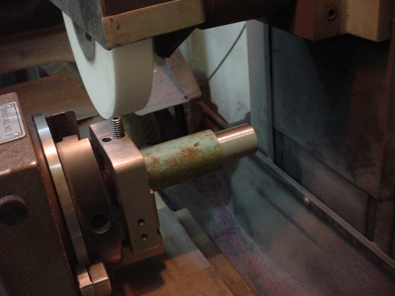
For the pulley I figured it would need to be heavy duty. Local steel place has a great selection and I got on bigger than I thought I needed and will turn the diameter to what I need later. Here I'm grinding it flat. It's 10.5" in diameter and almost 1.250 in thickness. Took some playing to get it flat but within a .001 now.
Drilled a 1/2 hole on the drill press and bolted it to a hardened ring. I'll turn it down to 7 inches and that was what I needed after everything else was in place.
I just eyeballed and freehanded a groove on the lathe to about a .500. Using .375 cable on the winch.
My lathe isn't good enough for pressfit stuff so my nephews helped me out. They used a boring bar on their lathe and got the hole in. While there they skinned .02 off the shaft for me and milled 2 holes for the pillow blocks in a 1 x 3 inch flat bar.
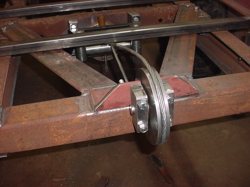
Slid a heavy 3.500" box beam in the frame extensions and will weld that in. Cut a slot for the pulley too. I'll have to angle brace it as there will be a good bit of force exerted there.
Wanted to use the box beam as a mounting surface and cable guide as the same time.
Slid the bar in the 2 blocks and grinding them flat/same here.
I drilled two .500 holes near the edges and thenused a cut off wheel to cut at the center of the hole. Cut 1/2 way through then flip it over. This is why I wanted them the same size and square.
Should be enough to keep everything tight and supported.
Welded some more 3/8" angle for the top mount hole. I'll strengthen these up too.
Trimmed the corners off and you can see I trimmed the shaft to size.
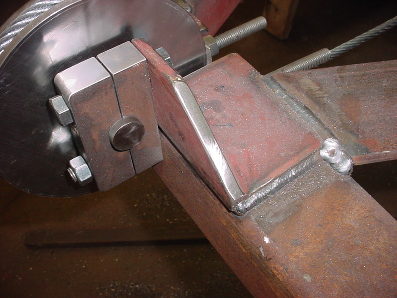
Braces are the same Angle iron and are bolted to the frame and welded at the rear. This way the whole frame extension can still be taken off in need be.
I'll do the rest of the final welding when I tear it down for painting. Cable height will have .250 above the final floor. Cable is going under right now just to get it out of the way.
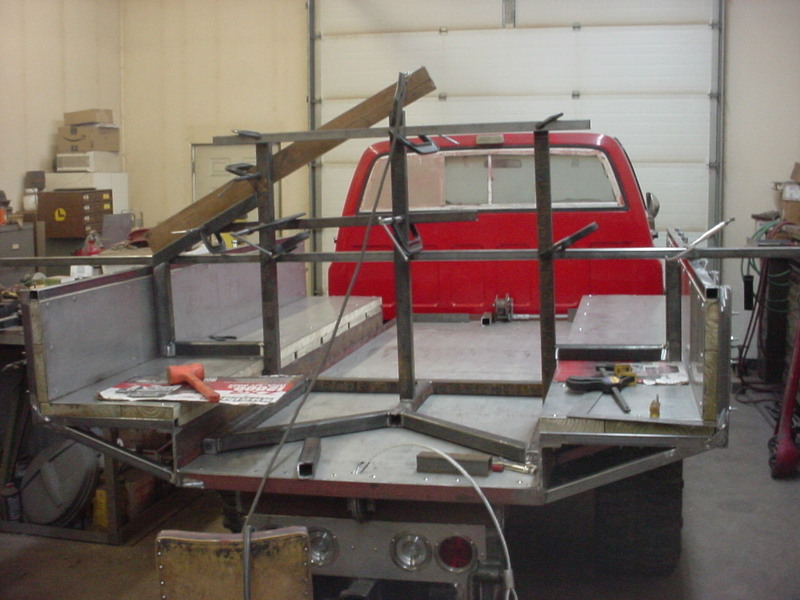
Since all that was done I cut another piece and decided on the final length of the bed. The top of this will be the floor height. I cut the siderails to length and welded it all in.
Relieved this one as well. I didn't want the pulley sticking out the back and this way it is protected some.
Decided I needed to put some support for the top bolts on the pulley so I found a small rectangle scrap and cut it corner to corner with a cut off wheel.
I cut it within .005 and break them apart by hand. This is what is left. Hit them with an angle grinder on the edges then and smooth with a die grinder and a soft pad.
Took less than a minute after cutting to get them to this.
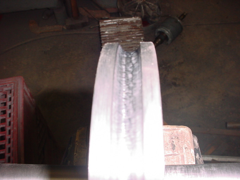
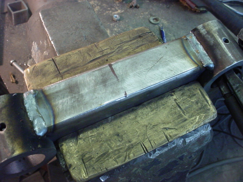
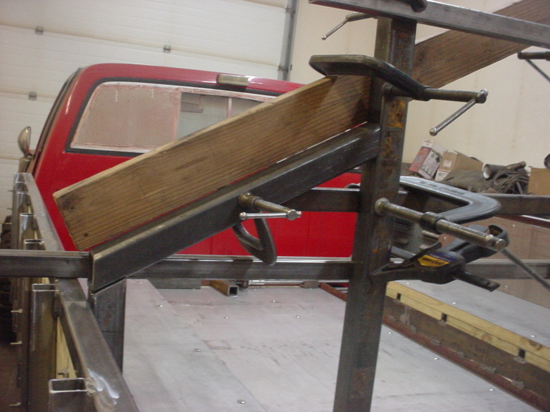
I need the sides to be higher so I can triangulate the bracing where the agled sides will be over the tires. I will stack another 3/8" angle on top of the other. Didn't have enough full length to do it so I welded on 2 shorter pieces and blended the welds. I had relieved both sides hard so there is close to 100% penetration.
Wanted everything plumb and straight so I used C clamps and angles to sandwich it inline.
This works really well and makes it nice/easier to weld.
I stitch welded this and would do a weld on the outside, then weld it on the inside at the same location. This keeps warping and pulling to a minimum.
One side done and pretty much dead straight.
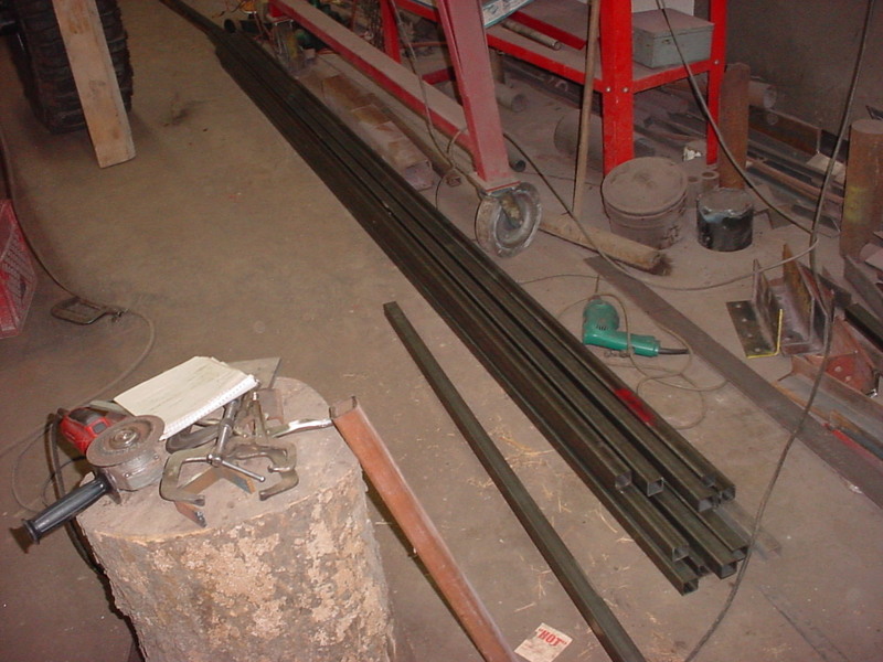
Got lucky as I needed to buy the box tubing. My local steel scrapper has a suoer nice used srell section all sorted and some under roof. They had this 1 3/8" box tubing that was cut around 12 ft in length as "used". No rust and new. I go there a lot and they cut me a deal at .85 cents a pound. Over 375 pounds for $315.00. New, off the shelf would have been around $1100.00 at todays prices.
Decided how far out and high I want so I will now make the outer sides. Carefully cut a 90 notch out as I have found it makes a stronger corner and easier to keep straight. I lay the pattern on the next piece, scribe the lines on both sides and cut with angle grinder with a cut off wheel.
Here it is in process. You can make really nice cuts with these and fast.
All of them cut now so I'll make up a jig for tack welding.
I first bend them all by hand. I use a square across the outer edges and twist, if need be with a pipe wrench.
Quick, easy and reusable jig to hold square. They will suck in more if you tack too hard in the inside corner. I like to tack on the top edge as it does less shrinking there.
Like this. I like a wider gap as when you fill, you have 100% metal there. If they are tight joints, you may not. I start welding in the middle and burst weld to the corners.
This is the same piece after welding, grinding and sanding with a soft pad.
I then cut up some angle gussets and welded them on both sides. Not as strong as pushing them on out but that would make what I have planned impossibe and make stacking harder.
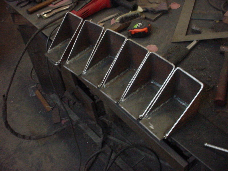
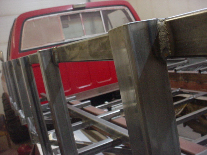
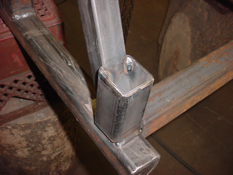
Finished all the inner corner welding and cleaned them all up. I welded the front and back ones on then used a box beam to help hold them in line while welding. One side done here.
I'm welding both sides of the box beam on these.
Checking the bottoms and nice an straight.
Other side on and after taking the box beam off, the tops are nice as well.
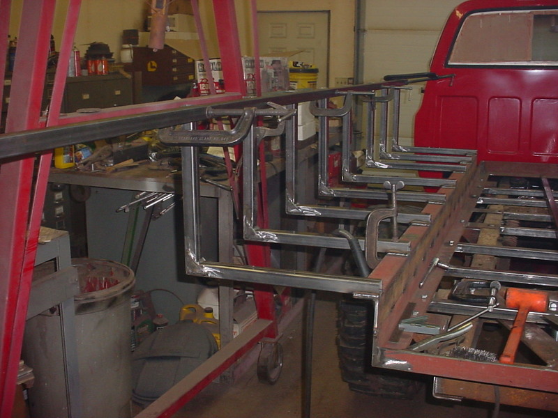
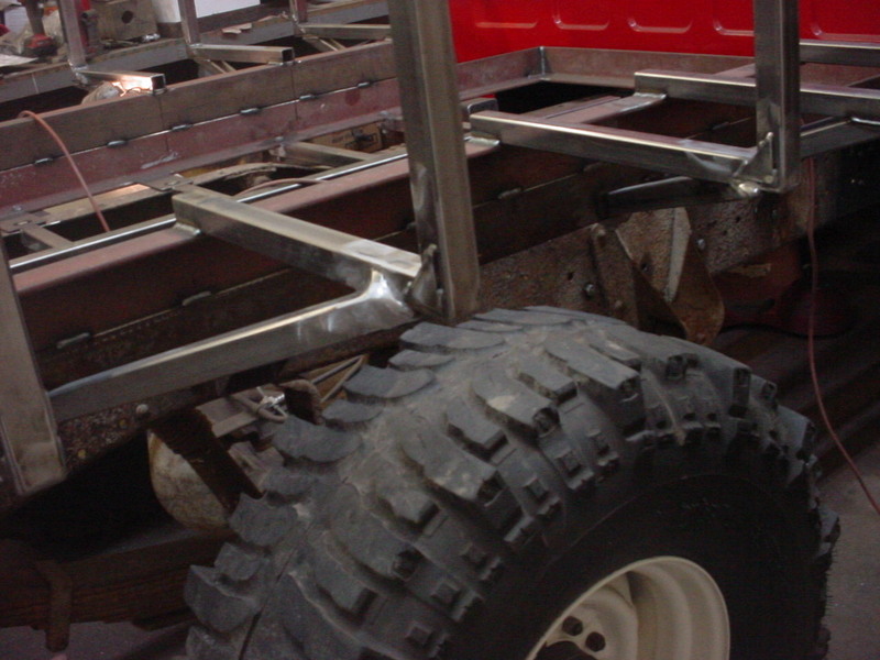
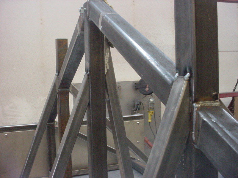
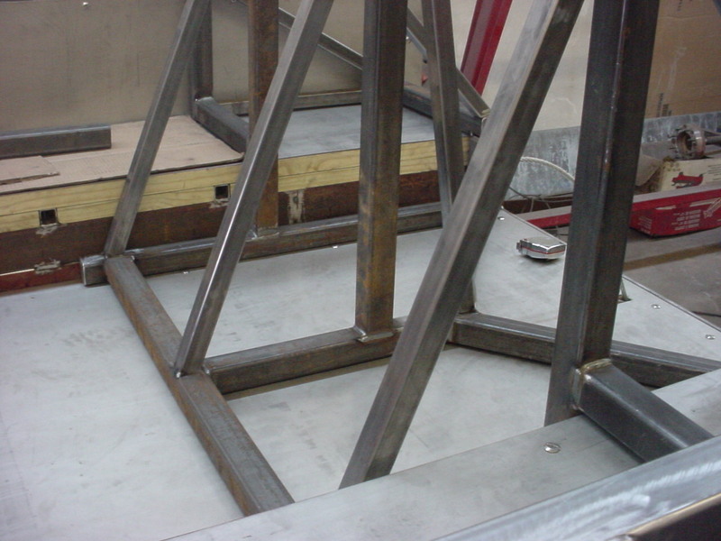
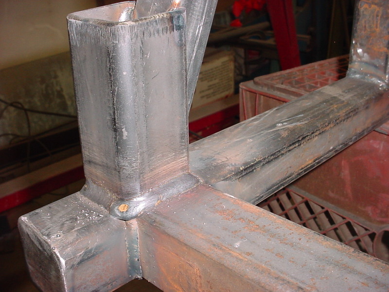
Putting angle braces on here. Triangulating the load to the bottom of the bed frame and it really helps the strength. I'll do all the top side and vertical welding on these now.
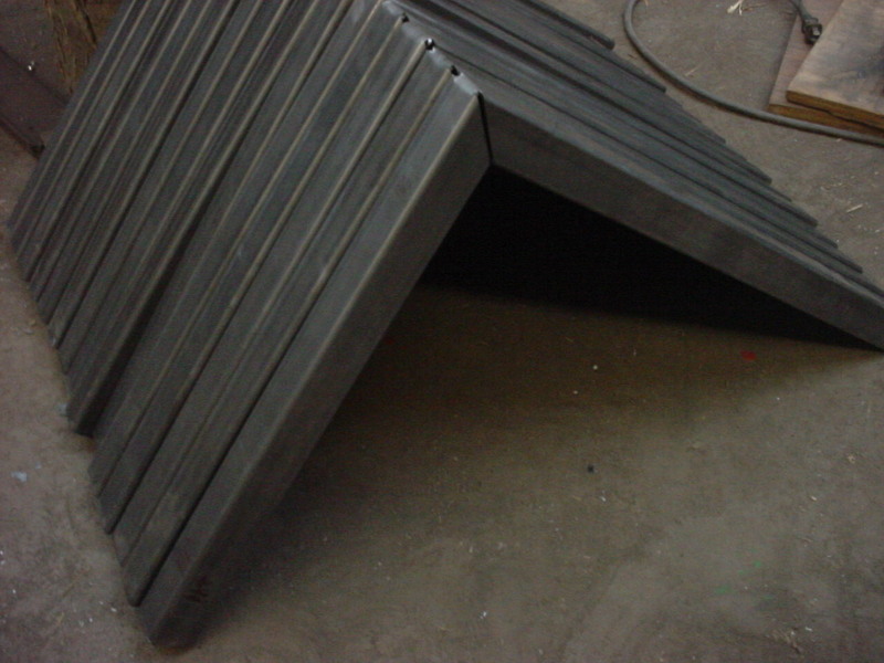
This is the other end. 12 were needed and made them all the same. The ones on either side of the tires will have compound angles so that will be fun.
Took about an hour but a whittled away at it till I had all the angles right. They need to slope away from the tires as if I made them like the others, the tires would hit with spring compression from the load. Here I'm cheating on the rest for cutting. Squared the rail to the table and transfer the lines
I use a square and mark the corner then connecred the dots with a scribe. Ink up the keep side and cut to the line with a cut off wheel. Since I kept everything the same, I'll need 2 the same and 2 mirror imgaged ones.
Seeing both lines allows you to hold the angle grinder right for the cut.
Here it is cut.
Very little adjustment was needed and then I welded it on.
Put in some sloping fill pieces so the self drainand have 7 inches of tire clearance at any point. 5 1/2 inches would be bottomed out so I have a little extra.
Next I welded both top rails on. Leaving the uprights open so if I want extensions, I can just slip them in. This is another reason why I notched the 45's on the bend. Any water or debris that gets in there can be washed or blown out.
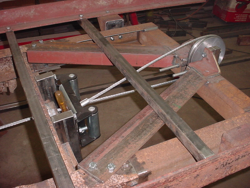
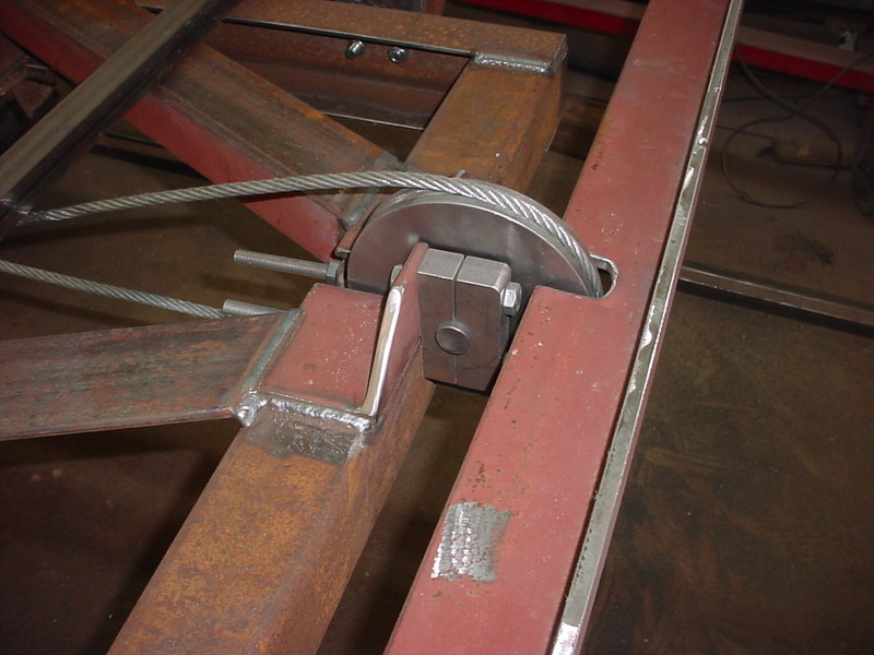
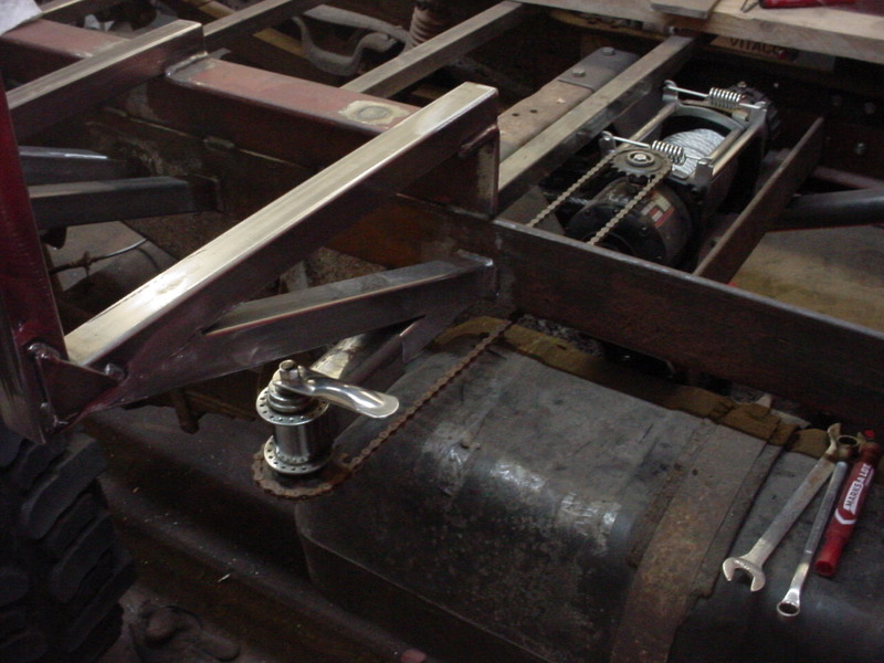
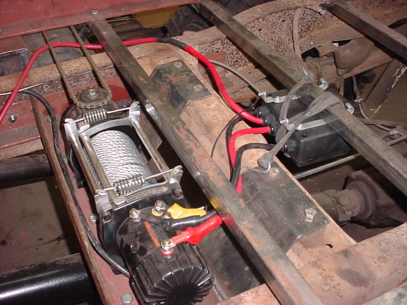
Have 2 things needed here to make it nicer. To pull the pusher back I mounted a hand winch. I also need to have a remote switching system on unspooling the winch as it's in the center of the frame. I'll address that first.
I'll have to make a new pin for switching it. Factory handle/pin is pot metal and figured this would be nicer. Started by spinning a shaft to clean to copy th inner workings of it.
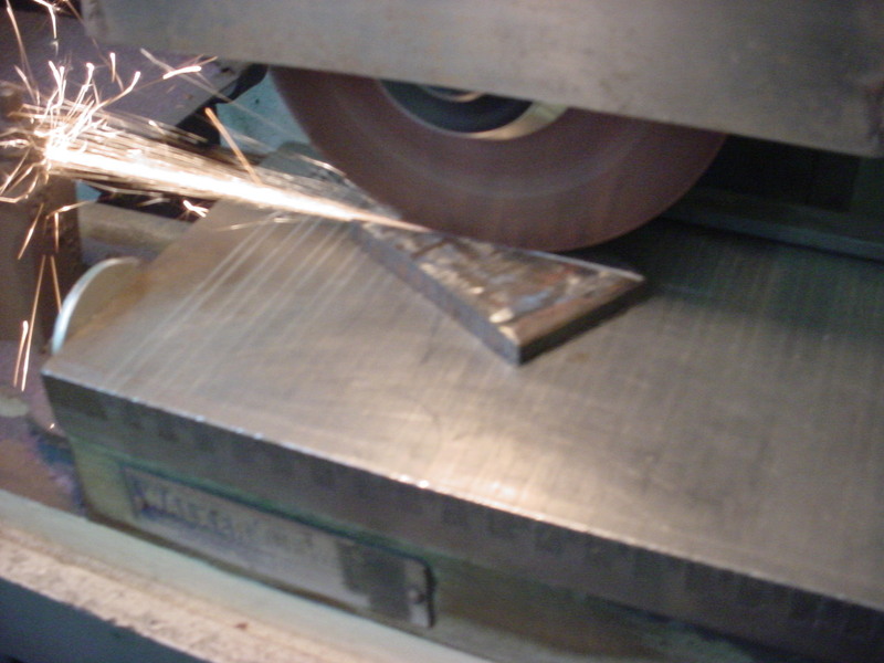
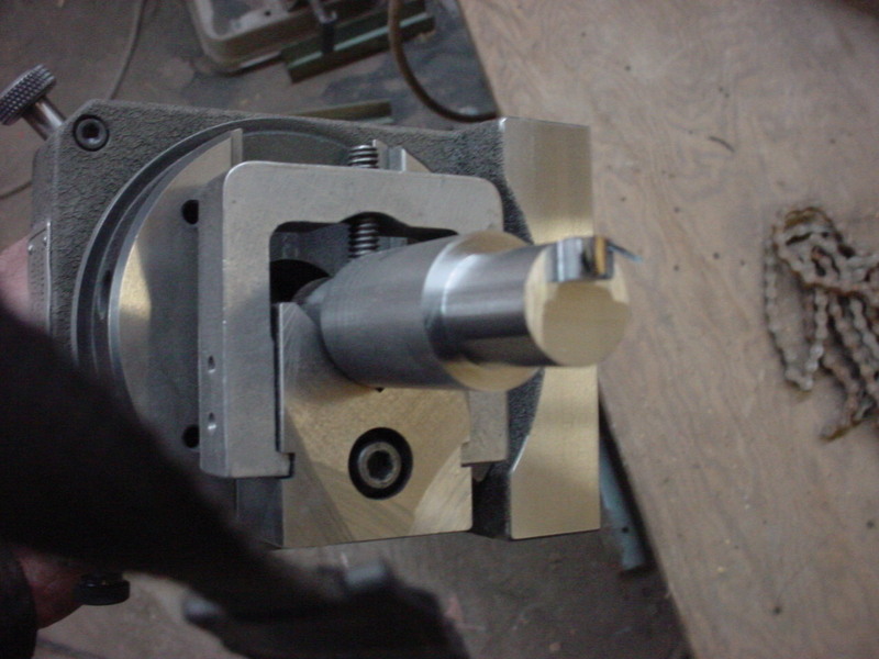
It has an offcenter round pin with a double off center slot, detent groove and an O ring groove. I started by grinding an off center square to .001 over diameter size.
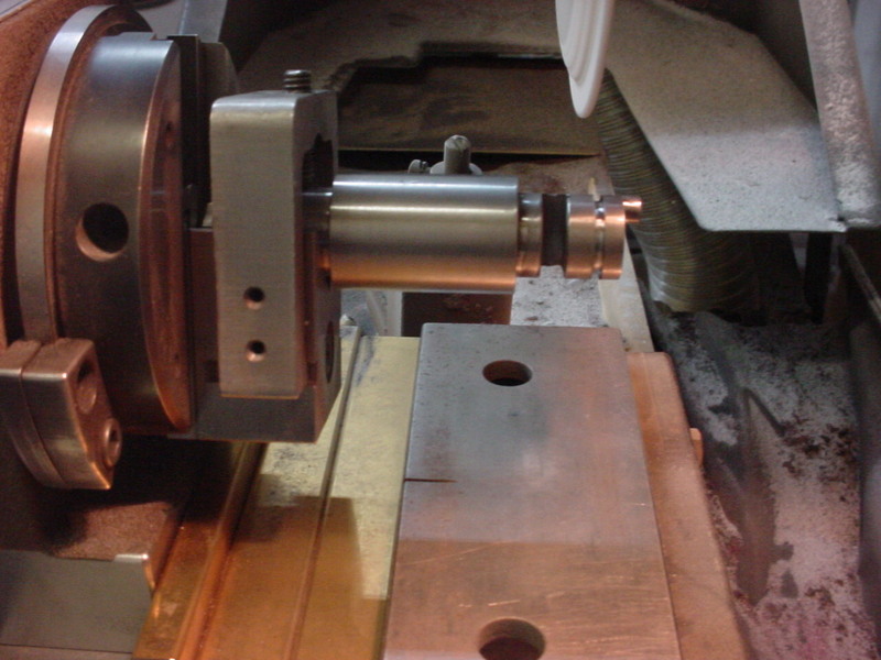
Then knocked it down in the Harig fixture till all flats were equal. Then spin it manually while downfeeding the surface grinder and bring it to size.
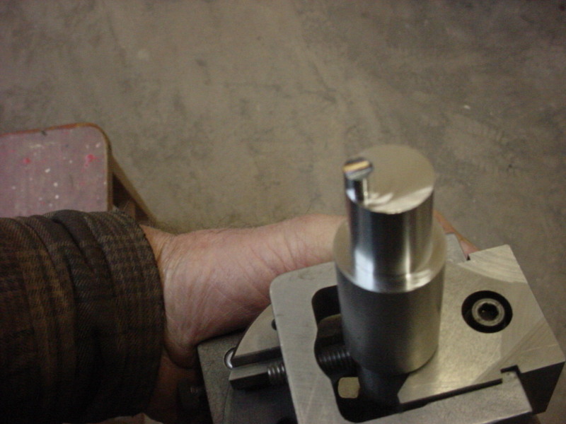
I ground a small flat which showed me center and center punched it. Then drilled through. Half will be ground away and this will be the detent internally.
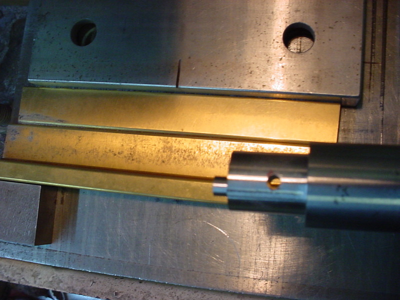
Here you can see the slot has been ground and spin grinding the O ring slot. Lots going on in this little piece.
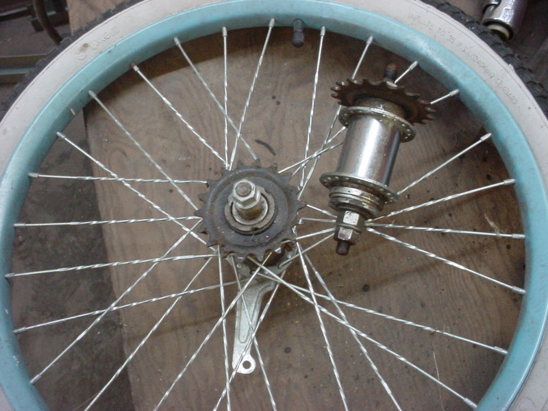
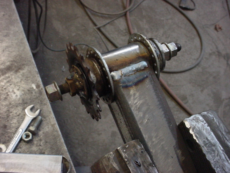
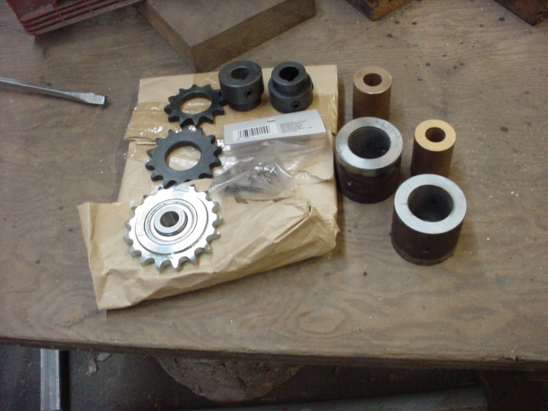
I'm going to use throwaway bicycle hubs for spindles. They have sprockets, chains and bearings so easy and nice. Iill dismantel them both. One I'll just use the sprocket and mount, the other I'll pull the coaster brake stuff out and lock the shaft to the sprocket.
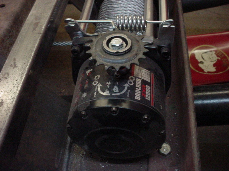
I then cut it off the holding tang and drill and tapped for a bolt. Then mounted a bicycle spocket using the hardened hub and installed it on the winch.
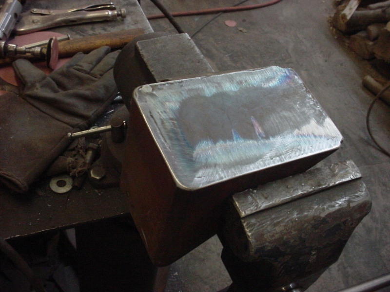
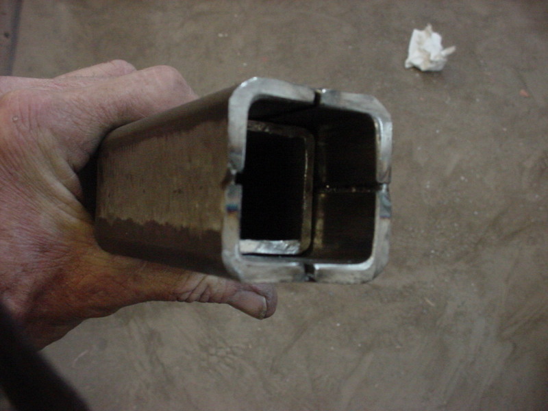
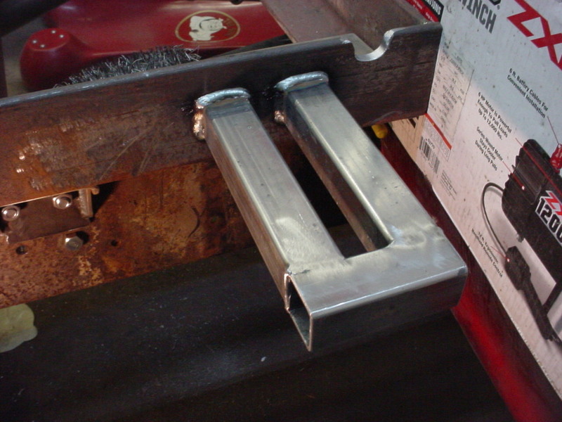
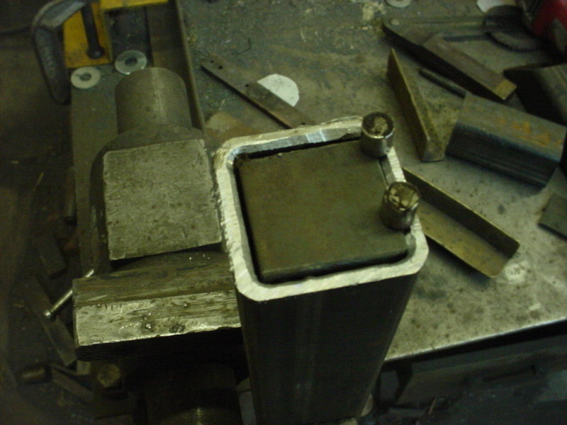
To mount the spindle, I decided on a box on box slide for adjustment tension. Cut a small bigger box down the length. Then wrapped 3 rounds of paper around the inner solid box and clamped the 4 corners. Tacked, then welded it back under low heat. Once welded, the paper is taken out(If not burned out) and you have just enough clearance. The grooves as you see are nice for grease retension.
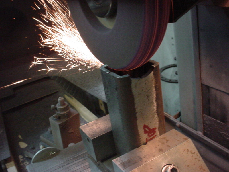
Ground a radius groove into the slide tube. This way it "seats in" for welding. I just ground away the outer edges as opposed to half wheeling a dress.
Now the spindle is true to the flats of the box tubing with it welded on.
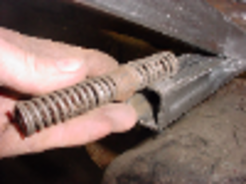
I put a wood block into the welded side and drill a pilot hole in the center. Then stacked springs to make the outer box spring loaded and it will always have tension on it.
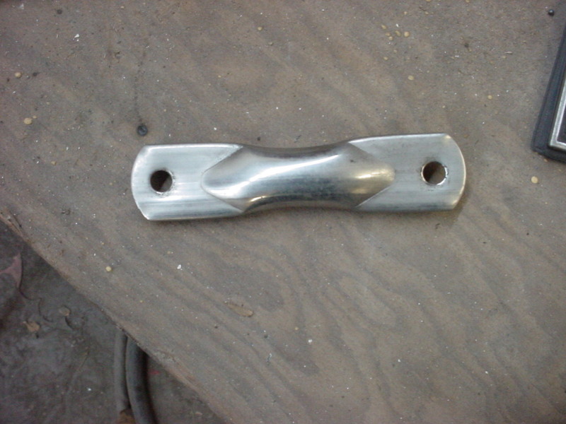
For a handle went to the junk draw and found a stainless rear view mirror arm piece.
Rounded one end and drill the other to 3/8" for the spindle shaft size.
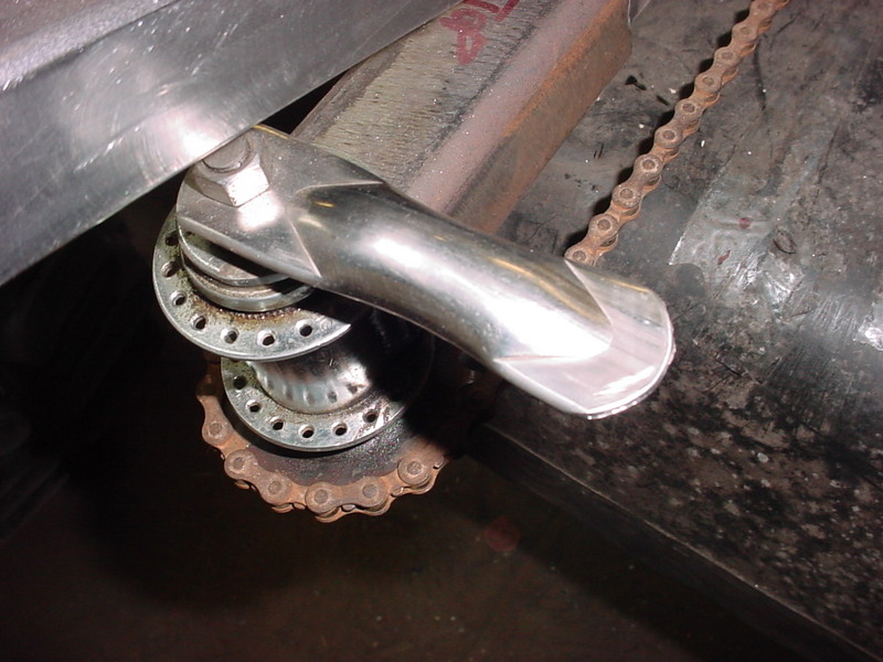
All complete and works really smooth.
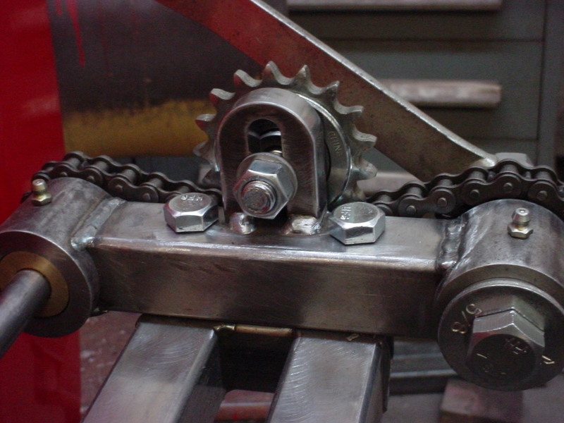
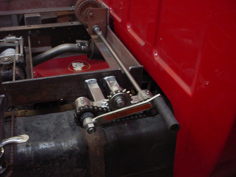
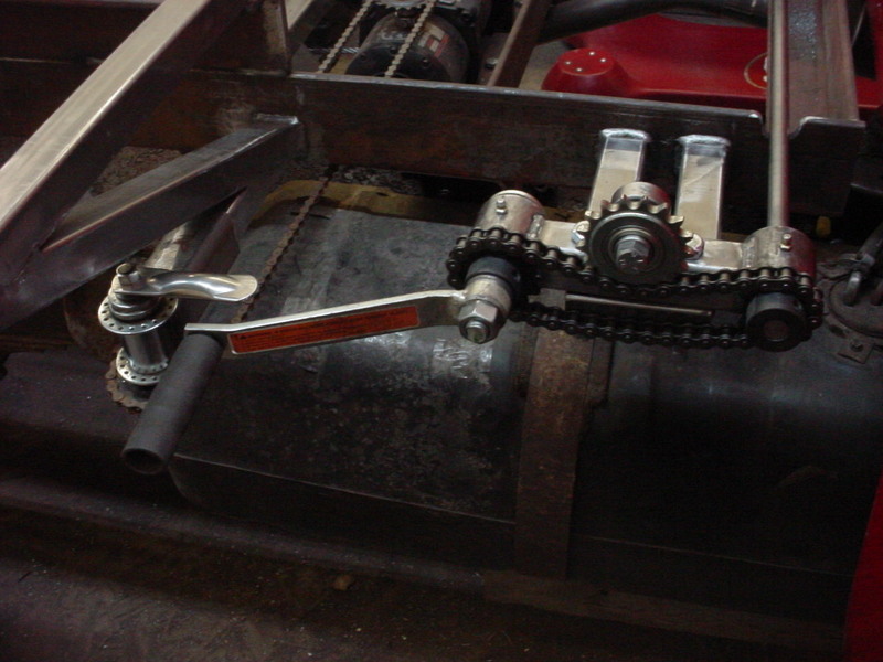
Next up is the offset for the crank on the hand winch. Rounded up some sprockets and drilled some round stock to accept some oil impregnated bronze stock I had. Drilled and reamed those to 5/8" which is the shaft size I'll use.
Measured the offset needed and made the center section the same way I did the winch switch. They will be in line that way. Ends are drill for a set screw on one aise and a grease zerk on the other.
Made a coupler for the winch side that is threaded, counterbored and cross drilled for a through bolt. Ground a hex on it to make threading on tight easy.
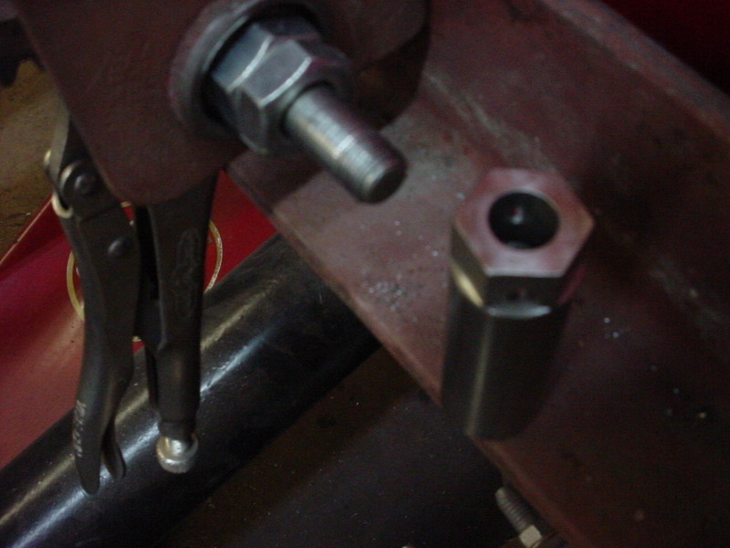
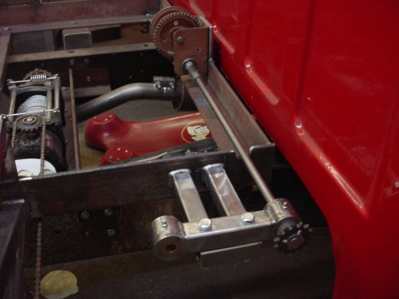
More measuring and made a mount to hold it. Wanted it stout as there will be some force pulling the slide back and unspooling the electric winch. I welded this on.
Once it was all lined up and smooth, I clamped it down and drilled two .500 holes for bolts.
Took a small piece of 1/2" flat bar and ground a groove down the center for a slide. The rounded the corners and welded it on for an adjustable idler mount.
All done and clears everything.
I may make the crank handle a break away later if I see issues with it. For now, I think it will be fine.
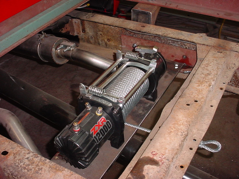
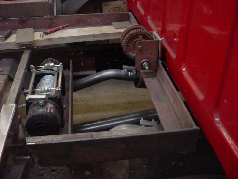
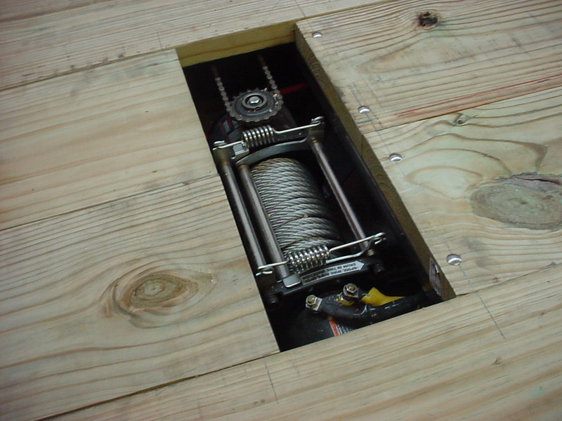
Extended the cables for the winch and hooked it all up. It all worked fine. I'll route and secure the cables later as well as the box once the bed floor is in and finished.
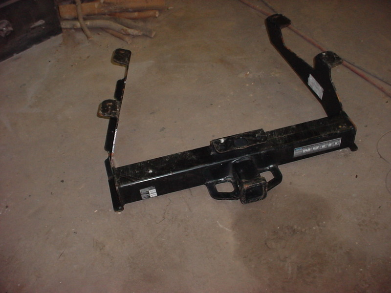
Buddy gave me a 2 1/2 Reese reciever mount he picked up for scrap. Never used but sides were bent. I straightened them out and started measuring.
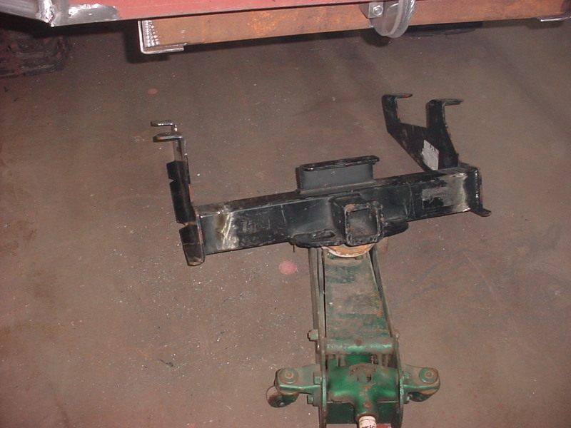
Ended up cutting 3 1/2 inches out of each side and reweldeing. Lifted it up and it has just the right amount of drop I wanted.
I'm welding this on the rear extension and will make up some more bracing now.
Got some 3 inch Box tubing that is .250 thick for the ends. Cut triangles out of the sides and bent the existing outer edge down. Rewelded it all and smoothed the rounded corners back.
Got my bracing in and partially welded. I'll finish the rest when I take it all apart for painting. 2 center pieces of box tubing in the center should add a lot of support to everything.
If I can do the welding in an easier position, it's a win win. Just makes it nicer.
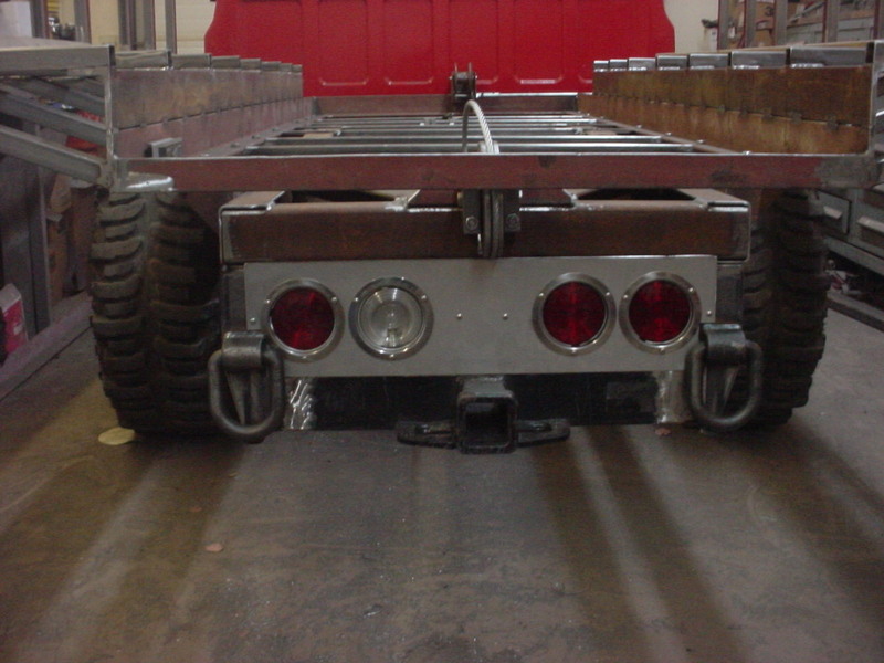
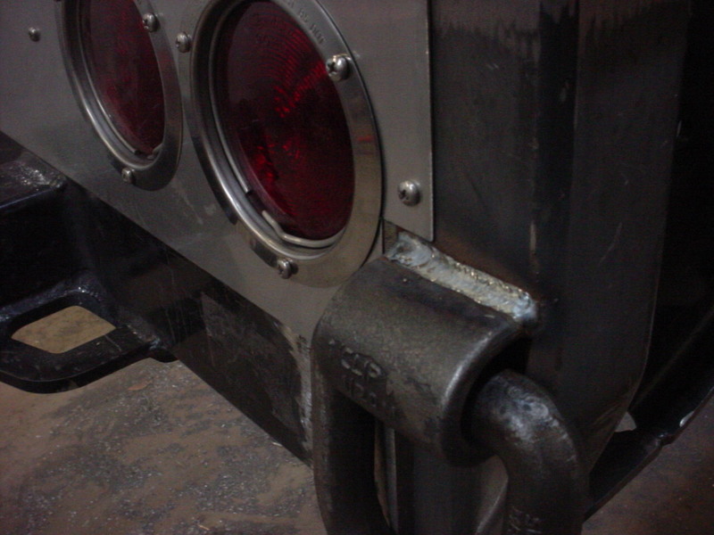
Mounted the flush mount lights I had in a stainless panel that will dress it up some. Only had one clear lens so I'll get another one later. Welded on some loops as well.
Always nice to have options for pulling/recovery.
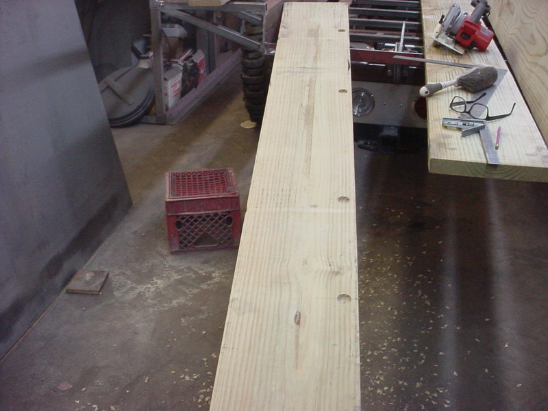
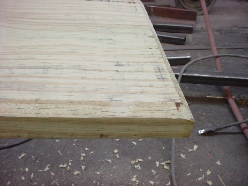
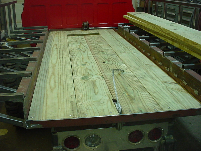
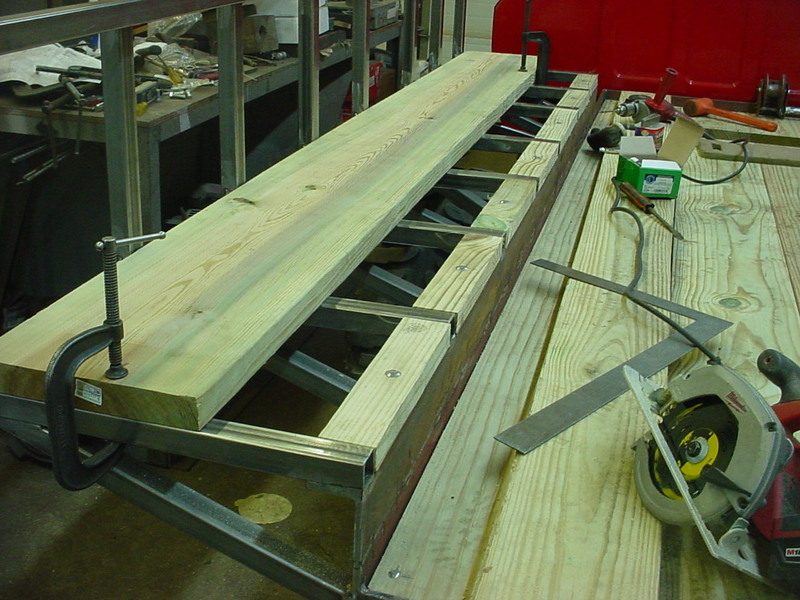
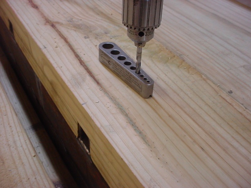
Went and got all the pressure treated lumber for the floor and sidewalls. Wanted the least amount of bolts so I got the widest boards that worked out with the measurements. Have some bolt heads sticking up so here I'm using a Forstner bit to clear those. Relieving the edges as well where the welds and curve of angle iron is.
Just putting small 45's on those edges.
Relieved it around the pulley and used a router underneath where the bracing for it stuck up. Using stainless carriage bolts to hold in place.
Cut some smaller pieces and filled in where the out braces are.
I used a rounding bit in the router so the boards would lay flat and still be snug on the ends.
Using this hardened tapping jig to keep the holes straight and hit the box tubing underneath in the center. You can drill a thick piece of steel too but this will never wear out since it's hardened.
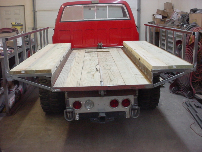
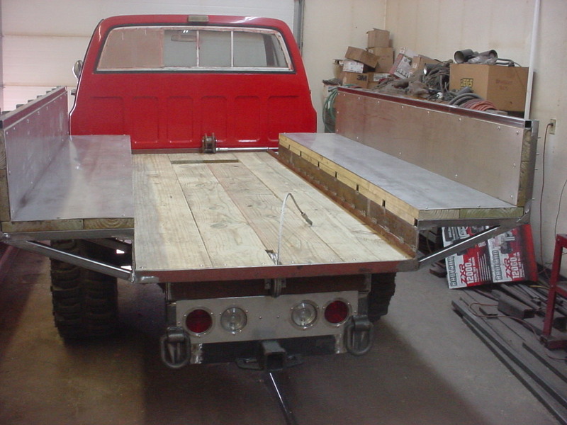
Wood is all down with just the sides to do. I think I'll put the metal on next so it will be held down by the upright wood on the sides.
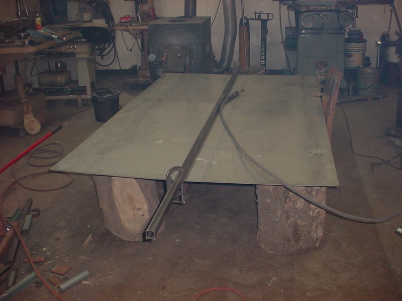
Using 12 guage stainless on the inside. This is a 5 x 10 sheet. Yes FIVE x 10. Local scrap yard had quite a stack of them. Set up some stands and clamped on a length of box tubing for a straight edge cut guide. Plasma will make quick work of this.
Sides are all done now. Waiting on some stainless sidewalk bolts to finish securing it.
I had a 4 x10 sheet of 12 guage here so it got the call. Cut the slot for the cable pulley and the winch access.
I used a cut off wheel for these and did it free hand. .040 wide cut and does a great job.
Making the push wall frame now. Using 2 inch Box beam. Bottom is 3/8" thick and uprights are 1/4". Tack them in the middle of all for sides, then the corners. Then finish weld. This keeps things from moving so much but you need to be quick.
Welding 2 shorts together here an using the angle iron trick again with C clamps holding it all straight.
Heavy reliefs, tack in the center of all 4 sides then the corners.
Keeps it all aligned and grind it flush with an angle grinder. This will be a pull piece with bracing so it's not going anywhere.
Nice and straight.
Since the roller doesn't stick out, I have to recess the pulling point so the slide can go past the end some. This will allow easier cleaning of trapped debris. Center crossmembers are about 1/4 inch higher than the slides so they don't drag. I just drilled a 5/8 inch hole behind the Y to attach the cable eye to.
Using a board as a guide to fit the top angles. C clamped Box beams serve to keep everything aligned for tack welds.
This will let the panel on the wall fit nice. I'm using 3/16 thick aluminum sheet for that. I will be putting cross bracing in to keep it from bending.
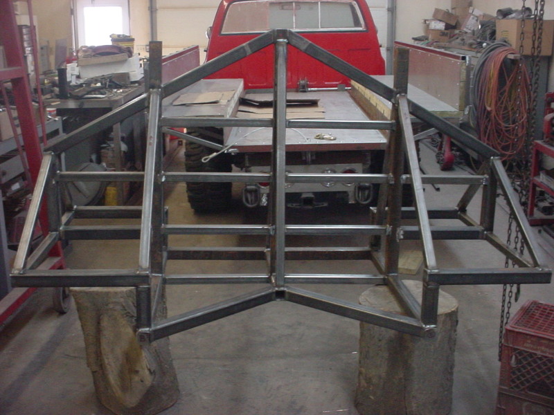
Got it all tacked then lifted it out to final weld this part. Now I'll work on the bracing for the side wing sections.
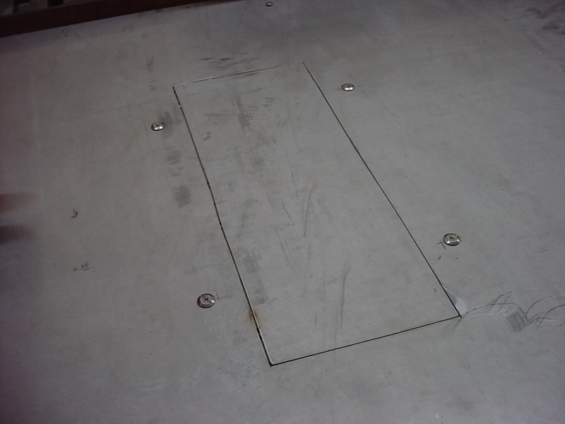
Here's a helpful hint if you want to close in something and keep it flush. I cut a scrap a little smaller than the hole but how do you keep it in place for tacks? Easy. Use a couple small magnets and it will be another set of hands for you. They will affect weld quality but for just tacking, it's fine. Notice I relieved the edges so you have more welded/fused area.
Tacked the 2 corners away from the magnets then slide them off quick and do the other 2.
Weld it all up.
Grind it flush.
Hit it with some 80 grit and no sharp edges. This will keep debris from building up in an open hole.
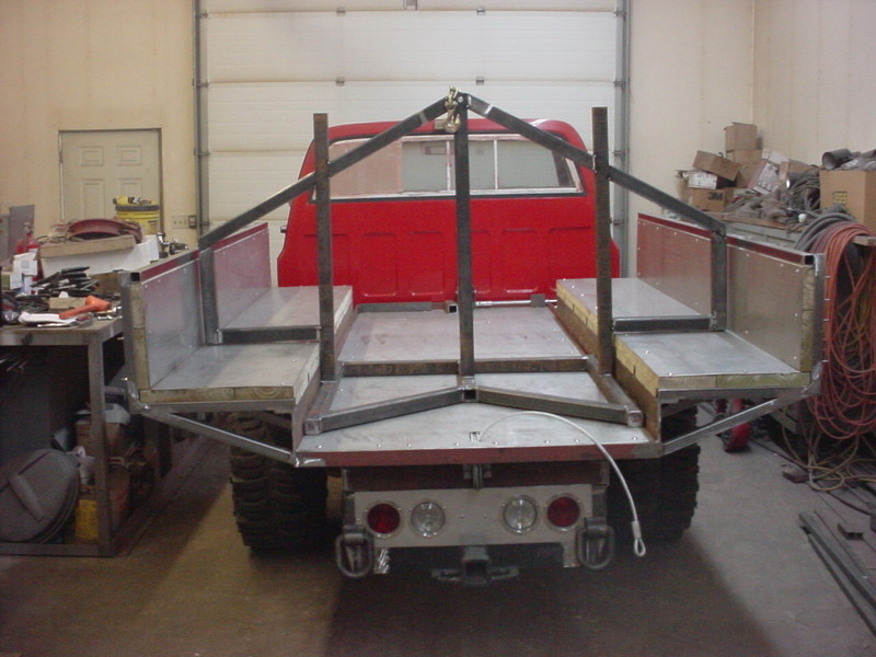
Measured and cut all the front angle braces. I tried to keep in mind making it as easy to load as I could. Can't get away from some of it as it will have some pretty stout load to push a cord of wood. just tacked them all here.
Kept all the ones on the back the same. I'm leaving the upright tubes longer and open. I'll store a shovel and broom in there and have a grommet on the handle to keep moisture out.
Another reason to keep the same is I'm going to enclose this on the back for storage. I can get supplies and a couple saws in there. Back supports for the wings is next.
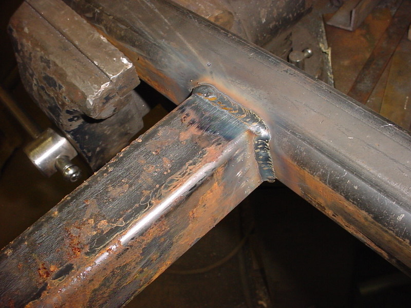
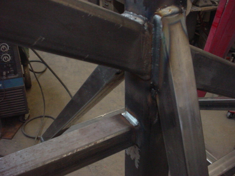
Slicing a larger box tube to go around the brace here.
I then slid it over the angle brace and welded it on.
There will be a lot of force pushing back and I didn't want a higher joint on those. To me, it would be a weak point.
All the lateral bracing for the push wall were cut and welded in at this point.