McCulloch 10 Series Oiler

Arborist Forum

Help Support Arborist Forum:

This site may earn a commission from merchant affiliate links, including eBay, Amazon, and others.
Joined
Dec 28, 2005
Messages
12,936
Reaction score
21,241
Location
Dike, Iowa
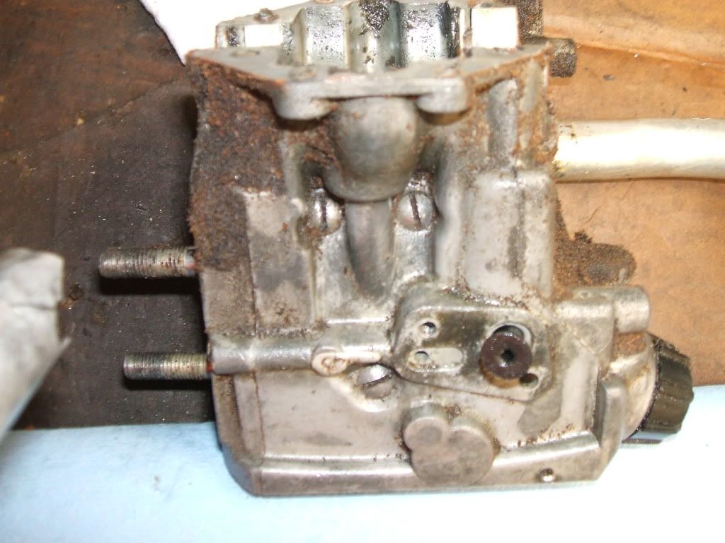
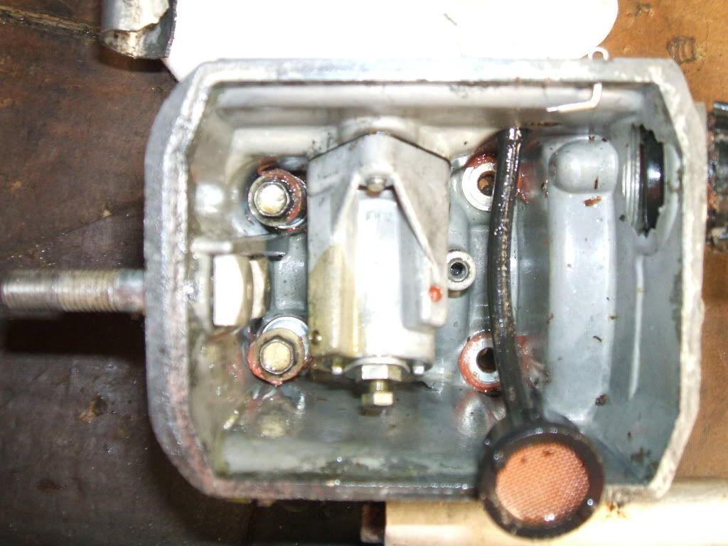
There have been a couple of threads lately discussing McCulloch 10 Series saws and oiler issues. I had a little time to take a few photos and thought I try to show how the parts are supposed to work.

The first attachments are the pages from the manual describing the oiler function. The only instruction missing is the the last note that says tighten the screw on the oil pump cover to 55-60 In/Lb.

Sorry, I don't know any way to load these .pdf files to make them automatically appear.

Mark
 
Next up are a couple of pages from the IPL's illustrating the differen oiler options. There were a very few 10 Series saws built that were manual oiler only. Notice the second (outlet) check valve in the small block that installs inside the oil tank where the automatic pump would normally go.

The automatic pump is probably more familiiar to most, but even the automatic had several different variations. None of the IPL's that I can remember show the "clip" that hold the bottom of the pump in place yet most of the saws I have worked on use the clip that wedges in the back of the automatic pump.

Many of the IPL's do show a metal retainer on the top of the automatic pump that springs against the bottom of the oil tank to fix the pump in place. Somewhere in the work shop manual it mentions automatic pumps with three screws (most have only one and some kind of clip or retainer) but I've never run across a three screw pump version.

Mark
 
Let's examine an empty tank. The hole in the upper right hand corner is for one of the screws that mount the manual pump. The ragged looking hole below and to the left is for the oil pick up line, and the cathedral shaped boss to the left of the holes is for the automatic pump. The large hole in the top/center is for the mounting screw, the smaller hole to the right is where the oil flows from the manual pump into the automatic pump, and the hole to the left of the large mounting screw hole is where the oil discharges to the bar and chain.

attachment.php


Next is a view of the top of the tank, large hole with the counter bore is where the pick up tube is located, the small hole in the oval counterbore is where the manual pump discharges to the automatic pump, the plugged hole to the left with the red sealer is how they make the oil passage from the automatic pump to the bar. The rear (or upper) mounting hole for the manual pump is threaded, the front or lower hole is for a screw that passes into the tank and is secured with a nut. The threaded hole to the left (at an angle) is for the automatic oil pump mounting screw .

attachment.php


The oiler discharges into a pocket that line up with the oiler hole in the bar. Again you can see a plugged hole that forms part of the channel for the oil to move from the automatic pump to bar.

attachment.php


Oil tank with the oil line installed.

attachment.php


attachment.php


Mark
 
As shown in the workshop manual, the manual pump is simply a piston, o-ring, and a spring. The black cap holds everything together.

attachment.php


The inlet check valve is a small disk, original equipment were mostly phenolic, later the part was made from aluminum. Roughly 0.300" diameter, thickness varies from 0.060" for the phenolic to 0.036" for the aluminum.

attachment.php


I set the aluminum one in the manual oil pump so you could see where it goes.

attachment.php


Here you can see the aluminum one on top of the inlet hose flange. The counterbore in the bottom of the oil pump is deep enough to allow the disc to "float" when the piston retracts, and seals when the piston is pushed forward when you operate the manual oiler button.

attachment.php


Finally shown here is the check valve on the flange of the inlet tube, and the gasket in place.

attachment.php


Mark
 
Last edited:
The manual pumps have been produced from a variety of materials over the years, including plastic and aluminum.

attachment.php


The manual pump installed viewed from the outside...

attachment.php


...and from the inside.

attachment.php


One of the interesting thing about the 10 Series saws, the oil tanks are very similar on the older non-antivibration saws and the later model SP and PM antivibration models even though the oil pumps look quite different. All the previous photos are the normal 10 Series manual pump on an SP81 tank. The photo's below are the SP81 oil pump on the SP81 tank, notice the tapped holes in the bottom of the pump for mounting the top shroud and flywheel cover.

attachment.php


attachment.php


If you want to "bench test" at this point you can try blowing and sucking through the pick up tube; you should be able to blow towards the pump but the check valve should operate if you try sucking (apply vacuum). I do this the crude and old fashioned way...I choose not to remove the screen from the bottom of the pick up tube as they are very difficult to reinstall.

Mark
 
Last edited:
Now on to the automatic pump. The pump is actually very simple, in hydraulic terms it is an "air oil intensifier". The large diameter piston is operated by crank case pulse pressure (up and down) and the small diameter rod is the oil pump. There is a check valve in automatic pump as well, a 3/32" diameter steel ball and a spring. On many versions the check valve can be disassembled and cleaned, but there are a few that are cannot be opened up. Below you see three different automatic pumps, the two on the outside can be disassembled by removing the adjuster screw and the cover under the screw, the one in the center cannot be opened. The one on the left has a kind of spring clip that presses on the bottom of the tank to help seal the bottom of the automatic pump against the top of the tank.

attachment.php


Inside the automatic pump from top to bottom: pump body, adjustment sleeve, a felt seal/breather, spring, piston, seal.

attachment.php


Inside the pump body you can see the adjustment screw. Turning the screw clockwise will limit push the adjustment sleeve and limit the stroke of the piston reducing the volume of oil the pump puts out.

attachment.php


The adjustment sleeve and seal/breather installed.

attachment.php


And on the other end of the pump, the outlet check valve assembly: pump body, check valve (ball), spring, cover, spring clip, and adjuster screw.

attachment.php


Mark
 
If the standard parts are used, maximum oil flow will occur with the screw backed out about 3/8". If you back it out any further, the screw simply withdraws into to body of the pump but the stroke is already maxed out. I normally start with the adjuster about one turn in from the maximum flow position. When everything is working properly that will empty the oil tank before the fuel runs out so I don't fill the fuel tank all the way to help balance things out.

attachment.php


I like to make sure the automatic pump is functioning before I put one together. It is possible to put some oil in the inlet hole and work the piston manually, after two or three fills you will see oil starting to pump up and out the discharge hole. It is also possible to test the check valve with a little pressure as I am demonstrating here.

Here I am putting the tapered end of my pressure tester in the outlet opening. Apply pressure and it should hold if the check valve is working.

attachment.php


attachment.php


Now that you know the automatic pump will work, you can install it in the tank. As I mentioned, there are two common methods for securing the automatic pump in the tank. One is the clip that is pressed "over center" and the other is the spring type clip on the top of the automatic oil pump.

Here is the spring version:

attachment.php


And here is the "over center" type clip on the left:

attachment.php


Mark
 
And there you have it, pretty much every thing there is to see and understand about the operation of the 10 Series manual and automatic oil pumps.

When the oiler stops working, as can happen when the saw sits for a long time or the system is loaded with saw dust, it may well be necessary to open the saw up and clean out the valves. However, before going to all the trouble of tearing everthing down you might try flushing the tank out with something lighter weight, I use mineral spirits since that is what I have on hand, other suggest kerosene or even ATF and some light weight oil to see if you can get it pumping again.

Most of the time, you can remove the cover from the oil tank and replace it quite easily without damaging the gasket or incurring a leak. If it comes to it, you can usually get the tank off the top without destroying any gaskets or the boot (anti-vibe models) if you work carefully.

Mark
 
Last edited:
One question... do you need to have the felt breather/seal in the oil pump? When I took mine apart the other day, it didn't have one in it at all.
 
Thanks for taking the time to write this up Mark. It will be a big help to lots of members this way when working on there Mac's!


Been awhile since I have done one of those oilers so it was a refresher course if you will for me.

Well deserved rep sent!
 
And there you have it, pretty much every thing there is to see and understand about the operation of the 10 Series manual and automatic oil pumps.

When the oiler stops working, as can happen when the saw sits for a long time or the system is loaded with saw dust, it may well be necessary to open the saw up and clean out the valves. However, before going to all the trouble of tearing everthing down you might try flushing the tank out with something lighter weight, I use mineral spirits since that is what I have on hand, other suggest kerosene or even ATF and some light weight oil to see if you can get it pumping again.

Most of the time, you can remove the cover from the oil tank and replace it quite easily without damaging the gasket or incurring a leak. If it comes to it, you can usually get the tank off the top without destroying any gaskets or the boot (anti-vibe models) if you work carefully.

Mark

You have the patience of Job, great work. Thanks for posting.
 
The earliest version of the oiler had 3 attaching screws from the outside, and did not use either spring plate on the inside.. It used the aluminum pump housing for both the auto oiler and the manual pump.
Here's pics of them:

DSCF3659.jpg


DSCF3661.jpg
 
PM610 - I expect there are as many 10 Series saws running without the felt breather as still have them in place, in other words no you don't have to have it.

mactodd - it has been a long time since I worked on on like that, indeed that was one of the earliest models with the automatic pump.

There is another version of the automatic pump with an aluminum body and a small screw in one of the back holes to properly locate it in the tank. I am not sure how these were supposed to be fixed in the tank since you can't use the "over center" clip and they didn't seem to have the much later spring clip on the top.

attachment.php


attachment.php


Mark
 
Great job Mark as always. I'd like to add that the smooth angled hole in the cathedral shaped boss inside the oil tank (unpanted section, with the ring shaped mark) is the impulse passage from the crankcase. There's a large elongated hole in the middle of the auto oiler gasket for for that passage.
 
Last edited:

Latest posts

Back
Top