porting the 044. what to do with intake and exhaust port

Arborist Forum

Help Support Arborist Forum:

This site may earn a commission from merchant affiliate links, including eBay, Amazon, and others.
Skirt Clearance

Just make sure not to go too wide, I've been doing it in stages, sliding the cylinder on and checking skirt clearance.

I am on my first port job. I have been needing help and finally found this post. :clap:

What is the "Skirt Clearance" exactly?:help:
 
Re to the Re: Skirt Clearance

That is from the edge of the port to the edge of the piston. keep it no less then .100" for normal work saws.

Ok Parrisw, so from the very bottom of the piston is the skirt. That makes sense because it does go down off the top of the piston like a skirt and I do refer to her as a female. I guess if a girl was running the saw she would refer to her saw as a male and she could call the skirt a kilt :kilt: lol :laugh: just kidding.

So the clearance between the skirt to the top edge of the intake port should be no less then .100" for normal working saws.
Correct?

Thank You for your Time :Eye:

No, the skirt edge!! to the side of the port. not the bottom of the piston, the sides of the piston. The skirt edge should go past the edge of the port .100"
 
No, the skirt edge!! to the side of the port. not the bottom of the piston, the sides of the piston. The skirt edge should go past the edge of the port .100"

So, the bottom edge of the piston should hang down covering the intake port by .100 restricting the flow :jawdrop:

:cry: Maybe you misunderstood my last post?
 
So, the bottom edge of the piston should hang down covering the intake port by .100 restricting the flow :jawdrop:

:cry: Maybe you misunderstood my last post?

No, I'm talking the port sides!! not the port bottom or top, the sides, the sides of the piston must cover the sides of the ports by a minimum of .100" If you do anything to the port bottom or top, it will change port timing, don't mess with that unless you have a very good understanding of port timing.
 
Here is my Stihl 440 Project Part I

I apologize for not doing this sooner. I also apologize if I upset anybody. I should have done this right away to let you all know what I am talking about. They say pictures are worth a thousand words so, here we go.

I started by making a degree wheel and mounted it to my flywheel:
View attachment 100836
Then I Zeroed the Piston at TDC using the side of the Casting for my indicator:
View attachment 100837
I checked to see at what degree my exhaust port was opening with my stock Jug and Piston by shinning a flashlight down my spark plug hole.
View attachment 100841
It opened up at 100*. I wanted to do this to verify what you all were talking about.
View attachment 100842
This concludes Part One of my Post for "Here is my Stihl 440 Project".
 
Here is my Stihl 440 Project Part II

At this point you all can see my concern. Here you can "BARELY" see the bottom of the stock piston through the intake port of my stock jug at the top of the port. This is the fully open position of the intake port.
View attachment 100850
The measurment on the degree wheel is 5*
View attachment 100851
I didn't turn the crank and installed my new big bore kit (piston and jug) on the casing and connecting rod. Here is a photo of what I got.
View attachment 100853
You can see the obstruction of flow in my unfinished intake port of my new big bore kit from the SKIRT of my piston. The fully open position of the intake port should be 5* right? That is what I was talking about earlier, was shaving the SKIRT (bottom sides of the piston) to be fully open at 5* BTDC. I wasn't going to change the timing by accident. I want to make it the same as stock like you guys tought me, understood?
I decided to turn my crank to 0* TDC to see if the port would open fully and it barely changed.
View attachment 100854
I can still see a obstruction of flow in my unfinished intake port when it should be wide open like my stock jug and piston.
View attachment 100855
This concludes Part II of "Here is my Stihl 440 Project".
 
Last edited:
Here is my Stihl 440 Project Part III

Even though I am not even half way through porting my ports out I wanted to see if I messed up my new big bore jug yet. I decided to check my timing through the exhaust port using a 100* setting.
View attachment 100858
I guess this is ok, I can barely see light at the top of the piston.
View attachment 100859
Now I figured it was time to measure my squish. I straightened out a strip of solder out directly above my wrist pin.
View attachment 100860
This is what I got for my smallest measurement in thousandths of an inch.
View attachment 100861
I think this is a good place to stop and wait for your input.

Thanks a lot fellas :popcorn:
 
Ok I have been reading all these porting threads and I am going to give it a try. I will widen the intake and exhaust ports blend the lower transfers and blend the upper tword the intake and clean the piston up. I will post pics in a different thread. I have a boatload of double cut carbide burs and I just ordered a bunch of sanding drums. Also Brad how wide is the slit in that aluminum rod like hacksaw width?
 
Just wide enough to fit the paper in. It's not critical at all.

My concern was it opening up in the port if its not strong enough for the centrifugal force the die grinder. But I have an 1/4 inch aluminum rod I slit it with a hack saw then squeezed it together and it seems to be fine.
 
thank you very much for the reply.

i will widen some. im just gona grind till i think it looks good and call it good. i just ground till it looked good on my 359 twice. think it might have a 3rd time comeing when i get bored

i have the cylinder here and man im lookin at the upper tranfer and ill leave it alone i can see me accidntly getn the cylinder wall. need little 45deg angle grinder it looks like

thank you again for the reply

thanks

Evan

I have been using a diamond coated thin kerf cutting wheel made by Dremel, its number 545 and can be mounted into any 1/8" chucked machine. It cuts and works well on the upper transfers, I have used it in a Dremel tool but prefer my cable drive bit holder as its much more compact.
Pioneerguy600
 
I used a 1/8 inch grinder wheel on my dremel flex attachment for the uppers worked great. Then like a fine one as well. With the uppers I just made the transition into the cylinder tword the intake port smoother not much longer at all. then on the bottom I really smoothed the transition as far up as I could get.
 
bumping oldies again...

Before
335332649_y4CwS-M.jpg


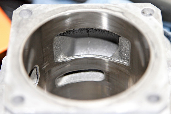
Do not take it out "into" the bottom flange. Just taper it to it. You really wouldn't even have to go that far. Just remove the lip often found at the bottom of the transfer and taper it a little to promote flow.

Quick question for the experienced guys...

Comparing this to the 066 jug that I have, the edge of the lower transfer on the right hand side in the pic above is much further away from the edge of where the skirt rides. It seems like the lower transfer is essentially centered between the edges of the skirts, which would seem to force the charge to essentially travel straight "up", then get turned towards the intake side by the upper transfer.

Do you think there's anything to be gained by blending the lower part of the lower transfer down and towards the exhaust side, essentially allowing for a more straight line shot to the upper transfer?

I know, I know, n00bs shouldn't touch the transfers - I'm just thinking out loud here..

for a work saw I wouldnt touch them
 
Back
Top