chadihman
Addicted to ArboristSite
Good point.
[video=youtube_share;zwdMSCJULgU]http://youtu.be/zwdMSCJULgU[/video]
There you go! Thats what I want. It would have been nice if the camera would have focused.


Good point.
[video=youtube_share;zwdMSCJULgU]http://youtu.be/zwdMSCJULgU[/video]
Alright men I'm out for a while. Going to cut some squish and base on the lathe. Got two MS 460's that I wanna get done.
A flywheel dyno is power up for a few seconds then your done. This is exactly what a women hates. Get it up then squirt your done. Longer up time is better.:msp_w00t:
The point in building a dyno is to learn if you are making power, and how much. If you just want to listen to it, go out in the woods and rip a log.
 opcorn:
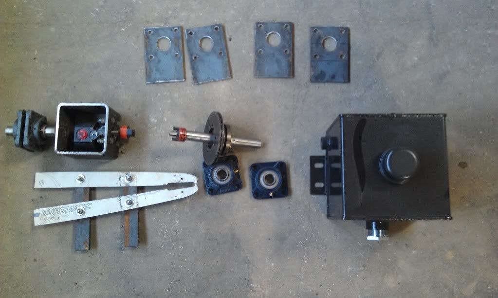
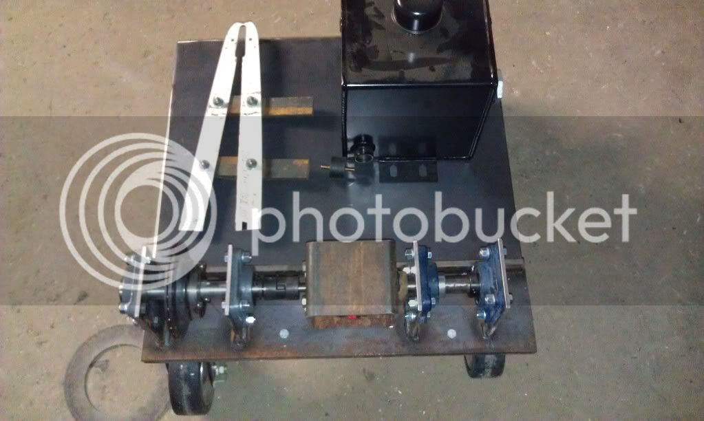
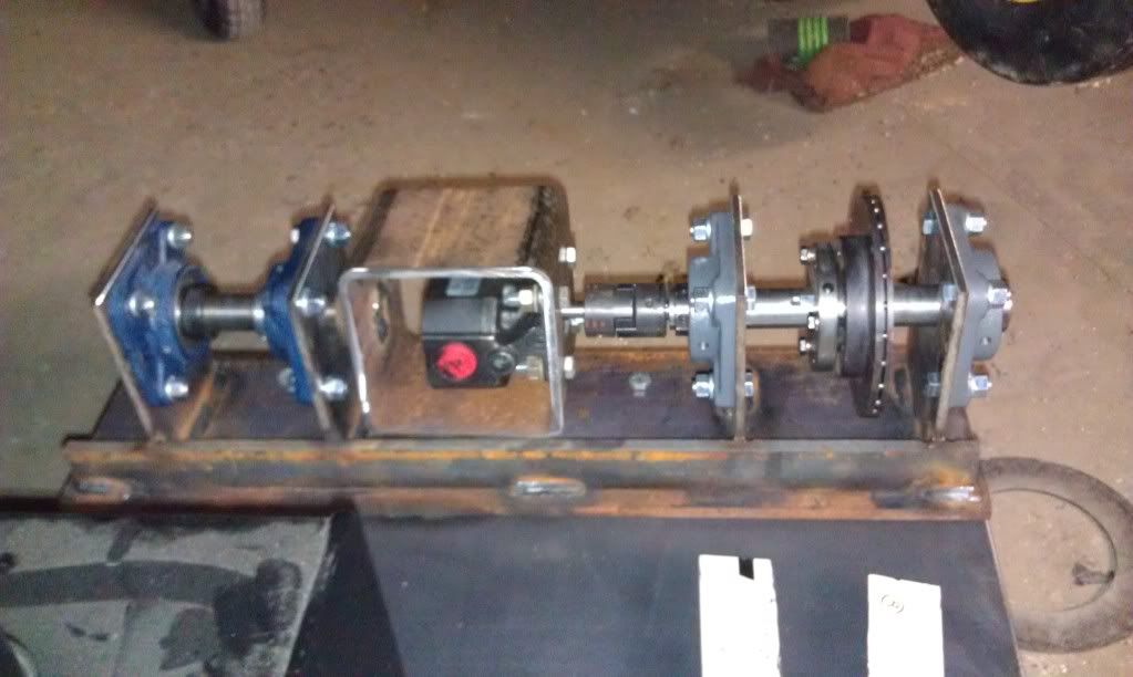
Chadihman, did you make or purchase that driven sprocket?I finaly got some time this morning to work on the dyno build. I had surgery and finaly made it back to work two weeks ago. Work has been crazy and had some long hours and was just to pooped to work on the dyno in the evenings. I'm going to work at it some more tonight.
My dyno is going to be used for checking power changes after making changes to the saw like port timing or ignition advance. A brake style dyno like the one I'm building should be nice for pulling the saw to different rpms and testing the torque at any rpm. This dyno should be the cheapest way to find the #'s I'm looking for.
Exactly. You can do the very same thing with a wheel. Hope it works as well as it is beginning to look. This is an interesting project.
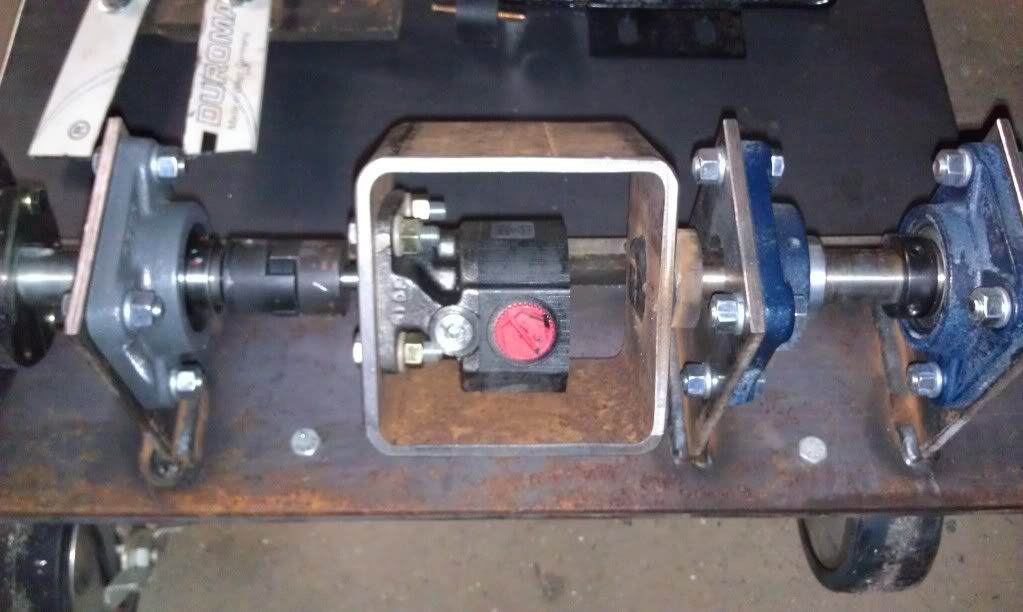
Could you please explain how you can determine torque at any rpm with a flywheel dyno? I'm guessing it takes an expensive monitoring system. Am I right in saying a flywheel dyno uses a heavy flywheel and the saw is timed on how long it takes the saw to get the heavy mass to a certain rpm. I guess that works for power testing but what im looking for. Changes could be made to the saw as its running the test with my style dyno. Air flow or carb adjustments would be nice to test underload.
Here's a dyno video of an engine blowing up on a dyno. Don't want this to happen to a freshly built chainsaw on the dyno. [video=youtube_share;aUkXriHjQeI]http://youtu.be/aUkXriHjQeI[/video]
On your scales, there will be considerable vibration whereby you will need to interpolate the average reading. It is easy enough even with a digital scale after you get used to it.
You may want to consider a buffer - if you are using digital input into a computer, for example?

Enter your email address to join: