New splitter - stress and twist problems

Arborist Forum

Help Support Arborist Forum:

This site may earn a commission from merchant affiliate links, including eBay, Amazon, and others.

sw18x

ArboristSite Operative
Joined
Sep 22, 2011
Messages
173
Reaction score
41
Location
NY
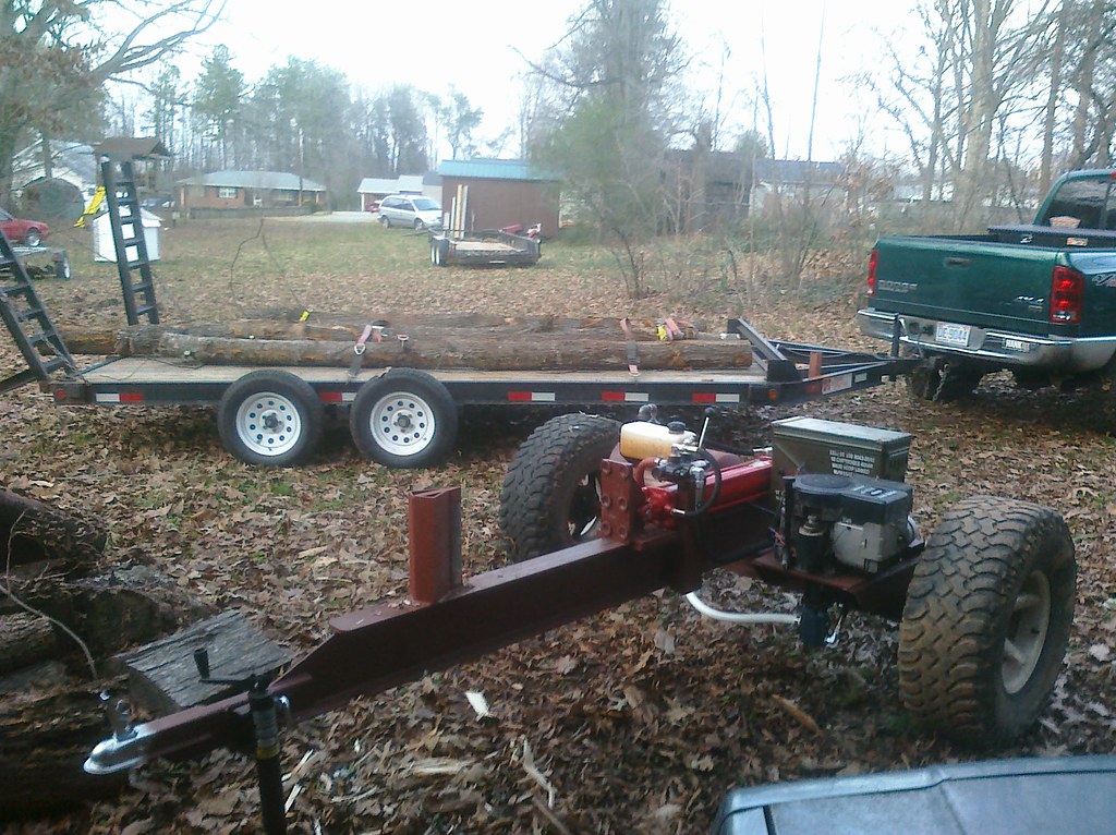
Splitter home build for OWB: 10' I-Beam, 7/16" web, 6.5" wide x 8.5" tall. 5” cylinder with 36” stroke, 11hp cast iron sleeve commercial briggs, 3000psi pump. Got it together and ran into problems right away. The wedge is welded to a plate which is in turn bolted to the i-beam. The entire wedge was trying to lift off the beam and started to bend the flanges, plus the entire i-beam was flexing (bowing). I was paying so much attention to the wedge end I didn’t catch what was happening with the pusher until it was too late. As you can see from the pics, the front edge of the slide bent. Should have seen that coming given the fact that, from a side view, the first bolt for the slide is three inches back from the front of the pusher.
The idea was, bolt everything together instead of weld in case something broke, so we could just remove the broken piece without junking the whole i-beam. That kind of backfired on us, given the fact that welding the pieces for the slide probably would have prevented that damage. I also think that part of the problem with the wedge was, all of the force was placed on 6 points (the 6 bolts) instead of the entire plate. If the plate was welded to the i-beam, maybe the force would be more evenly distributed. On the upside, the flange is only slightly bent in 2 places and can be ground flat, and the bent parts can now be removed for re-fab. Here’s the new plan, please share your thoughts on this:

1. I bought two 48” x 3” x ½” pieces of stock. I’ll be welding these on top of the i-beam side by side to strengthen the flange. Instead of 7/16”, the flange will now have an effective width of 15/16”. The pusher rides on top of the new stock, so I’ll be raising the rear mount for the cylinder accordingly.

2. I bought new stock for the slide. Instead of the lower slide (the part that rides on the bottom of the flange) ½” thick, it will now be ¾”, and all pieces will be welded together, no bolts, so the slide and pusher will be one piece. The front of the push plate is minimally bent, we’ll fill the gap in with weld.

3. Not sure yet what to do about the wedge. First of all, I plan on welding everything directly to the i-beam (see above). But unlike the splitter I used last year, the big pieces I tested on the new splitter were getting hung up right at the beginning of the split, then violently popping free. One piece got hung up in the first 2 or 3 inches, when it let go both halves of the wood literally flew off the end of the splitter in mid air. The wedge is home made and isn’t as sharp as a pre-fab wedge, it also flares out wider than some of the other wedges I’ve seen. Also, the weld at the base of the wedge in the front creates a wide spot which might be catching the wood. I thought the bolt heads might be catching but visually that didn’t appear to be the problem. I’ve got a store bought wedge which I might use to completely replace the home build. It has a much thinner profile.

4. Stiffening the entire I-beam. I read through another thread on this so I know it’s been discussed before. My thought was to weld another section of i-beam to the bottom of the current i-beam. This second i-beam is a little smaller, maybe 5”x6”. What about turning this i-beam so the two flanges weld to the bottom of the main i-beam? By my thinking, that should double the strength because rather than a single web reinforcing the main beam, you now have two points of reinforcement.
 
First off, if you were trying to split a round taller than your pusher - most of the force will leverage the push plate back like your picture. the flat plate ridge at the bottom of your wedge is also a problem. I really could not tell how high your cylinder is set but it needs to be as low as possible. Its best to have the slide plate of the pusher twice( in length) as height . If you box the beam that will help in the twist and flex dept.
Have gone through all this on my splitter before I rebuilt it ( destroyed the beam just like your description), I made my new beam out of 2, 4x6 x1/4 walled tubes welded together and a 3/8 x 8" wide top plate welded on top of them. My wedge is at the end of the beam it passes through the top plate and is welded to the tubes and then to the top plate. A thin wedge several inches in depth and then a spreader will reduce the force transmitted into the beam a considerable amount. I have not managed to bend anything up to date, although I have snapped some of the 1/2" bolts that hold the keepers/guides on to the push plate. Once in a while I will see the beam flex just before a very nasty knarly piece pops, My unit is capable of shearing a piece of oak in 1/2 ( cross grain) without dammage although you can see flex from the strain, but not beyond its elastic strength which is when damage occurs.View attachment 244956
 
Advice embedded:

... Here’s the new plan, please share your thoughts on this:

1. I bought two 48” x 3” x ½” pieces of stock. I’ll be welding these on top of the i-beam side by side to strengthen the flange. Instead of 7/16”, the flange will now have an effective width of 15/16”. The pusher rides on top of the new stock, so I’ll be raising the rear mount for the cylinder accordingly.

Adding additional thickness won't hurt, but I would definitely say you need a longer slide to prevent binding, at least double the length. In my opinion, you are trying to correct the symptom instead of the cause. I was using a splitter with 3/8" flanges and a long slide and never had a problem with distortion.

2. I bought new stock for the slide. Instead of the lower slide (the part that rides on the bottom of the flange) ½” thick, it will now be ¾”, and all pieces will be welded together, no bolts, so the slide and pusher will be one piece. The front of the push plate is minimally bent, we’ll fill the gap in with weld.

Bolts are fine, you just need more of them, and decrease the force exerted on them. See above.

3. Not sure yet what to do about the wedge. First of all, I plan on welding everything directly to the i-beam (see above). But unlike the splitter I used last year, the big pieces I tested on the new splitter were getting hung up right at the beginning of the split, then violently popping free. One piece got hung up in the first 2 or 3 inches, when it let go both halves of the wood literally flew off the end of the splitter in mid air. The wedge is home made and isn’t as sharp as a pre-fab wedge, it also flares out wider than some of the other wedges I’ve seen. Also, the weld at the base of the wedge in the front creates a wide spot which might be catching the wood. I thought the bolt heads might be catching but visually that didn’t appear to be the problem. I’ve got a store bought wedge which I might use to completely replace the home build. It has a much thinner profile.

In my eyes, the wedge appears too tall and just exerts extra force on the end of the beam, but it's hard to tell by the pics. With what you have there, I would say that anything over 8 inches tall is unnecessary. As for the leading edge, either use a single long thin wedge to 'slice' the splits, or use a thin leading edge that starts the split then gets wider after 2-3 inches to 'pop' the split the rest of the way.

4. Stiffening the entire I-beam. I read through another thread on this so I know it’s been discussed before. My thought was to weld another section of i-beam to the bottom of the current i-beam. This second i-beam is a little smaller, maybe 5”x6”. What about turning this i-beam so the two flanges weld to the bottom of the main i-beam? By my thinking, that should double the strength because rather than a single web reinforcing the main beam, you now have two points of reinforcement.

I don't think your beam is excessively flimsy, but I would make the other changes first and see how the beam reacts to the reduction in stress. Boxing both ends of the beam will probably make a noticeable difference in how the beam reacts to loading and unloading during splitting.


Jay
 
The problem with the wedge is that is is exerting force on the weakest part of the beam, out near the ends of the flanges where you have ti bolted. The bolt holes weaken it even more. The center, over top of the web is much much stronger. I welded my wedge on the top flange directly above the web so that all the force is put into the strong part of the beam and I have never had a problem, even with round much larger than the wedge is tall.


6640832233_6668d8e07c_b.jpg
 
All good advise!! I would take advice on the pusher plate having "wrapped" around the beam and bolt to the side instead of through it. Your wedge is the most stressed part ans should be welded through the beam and around the web. Your beam looks plenty strong enough. Check out the splitter pic thread in the wood burning section for some idea's. There are TONS of nice splitters built by guys on the site who are good at advice!! GOOD Luck on your build, when you get it worked out, there is no finer feeling than making life easier with your own designed tool!!:rock:
 
Also, you might want to consider"wings" on the sides of your wedge to force the wood apart more, stringy wood can be a fight with a "thin" wedge, just a suggestion.
 
Last edited:
Fixing bent beam

Here's what I did to repair my bent beam and tweeked push plate. Ended up cutting out a section of the top plate of the beam and welding in a thicker plate. Added a few gussets and built a new push plate from scratch. Still going strong, no bends, doesn't twist at all, straight up and back every time. Check out the link below.....

http://www.arboristsite.com/firewood-heating-wood-burning-equipment/185206.htm
 
Thanks for all the input. Another idea I had: the local steel supply house usually has 4 or 5" round "slugs" of 1/2" or 3/4" stock, I'm thinking of grabbing one to weld onto the front of the push plate level with the rod so the force isn't leveraged at the top of the push plate when splitting larger pieces. Ultimately my fix will incorporate some combination of the above ideas. I like the double tube design but for now I've got to much time and money tied up with the I-Beam to start from scratch.

Another question: I've decided to scrap my home build wedge for a pre fab with a sharper edge. Should I weld this one to a section of steel plate, then weld that plate onto the I-beam similar to my current design? Or weld directly to the I-Beam above the web (yours looks tough Awspence but I get some monster pieces from the tree service and I don't want to risk any more bends). What's the general consensus on this?

And finally - I know a guy with this wedge for sale (see pic). I like the "2 stage" design, problem is he says its part of a 4 way wedge he got from Timberwolf and I think he's going to want more than i'm willing to spend for the whole thing. Due to the size and shape of the wood I get from the tree service, and the fact that with an OWB I don't need to break the wood down into small pieces, I will almost never use the 4-way. Does anyone know where I can buy this type of wedge, just the vertical wedge, no 4 way? Thanks.

View attachment 245102
 
Last edited:
Personally I’ve never understood the idea behind large push plates and tall wedges.
Think of the wedge like a lever lifting a load, the longer the lever the less force it takes to lift the load… so a taller wedge has more “leverage” to bend the beam, break welds, etc.
A large push plate can place lateral force on the ram (trying to bend it) and “levered” force on the beam, slide, etc.
My thinking is the force should be kept directly in line with the ram… a much more efficient use of the force (little or none of it is wasted on twisting and bending of other parts). My splitter uses a small, round, floating push plate (about the size of my palm) that “grabs” angle-cut rounds and keeps near all the force in line with the ram. I have no problem splitting any diameter round (I’ve had rounds over 30-inches diameter on it).

attachment.php


attachment.php


attachment.php


attachment.php


attachment.php
 
Exactly. My buddy built the push plate and I don't want to hurt his feelings but...you could literally see the high push plate act like a lever as the beam flexed. I like the swivel on your pusher, when I add the round slug to mine it should keep most of the force in line with the cylinder.
 
sw18x,
Your present wedge will work if you put in some gussets between the top and bottom flanges of the beam.
The Timberwolf wedge is not a 2-stage wedge or even intended to be one. It was designed that way for their 4-way adaptor. Once the 4-way is slid on, the wedge sticks out beyond the bottom of the single wedge, reducing original stroke.
 
Thanks Triptester, I just found a thread with some pics of that Timberwolf setup. If you look back at the pic I posted, what I couldn't figure out was: what the heck is that 1/8" plate welded on the back of the wedge for? I think I figured it out. The guy I'm buying this wedge from bought it directly from Timberwolf for a splitter he never built. I'm betting Timberwolf tack welds those plates on in order to locate the wedge level and upright while they're welding it onto the beam, then they grind off the tack welds and throw out the plate once the wedge is welded into place.

Another question though, for anyone using the Timberwolf style wedge: do you see an advantage over a straight wedge when using the single blade wedge without the 4 way adaptor? What I mean is, does the lower section do a better job of starting the split at the bottom of the round, as opposed to a straight wedge which will try to start splitting across the full face? I look at it this way - when I'm splitting by hand with an axe, if I get a tough piece to split sometimes it helps to nibble on the outer edge of the round first. Just wondering if there might be an incidental advantage to that kind of wedge design.
 
Stepped or angled wedge will help reduce stress loads. stepped wedge not a cost effective option for mass market sales ( read how cheap can we make it to maximize return) I have had a straight angled wedge ( bottom ahead of top slope) but do not recommend that style as the rounds tend to ride up the face of the wedge, real exciting to see a 30" round pop out of the splitter. The stepped wedge with the leading edged ahead on the bottom makes sense, but leaves that amount possibly un-split above it, in the case of stringy stuff or knarlly knots. So there are trade offs. Almost everyone uses the "traditional I-beam configuration or a Y style in the case of one mfg. I went out side the box and used twin rectangular tubes side by side so you could say it is a fully boxed I style beam. It has been working well and was less cost than a comparable section of I shaped beam.
 
Here's some pics of the rebuild so far. The new pusher is 10" wide X 6" tall. The actual pusher plate is 1.5" thick, the base for the pusher is 3/4" plate, and the pin block is 1". We were going to add braces on either side of the pin block but once we had everything welded it didn't seem necessary - that pusher is mighty beefy.

As for the slide: after grinding down the high spots on the I-beam flanges, we welded a 4' x 10" x 3/4" plate on top of the existing I-beam. That left 1 3/4" of plate overhanging the old flange. The new slide consists of the new pusher plate base (3/4" thick), the "sandwich" (3/4" thick), and the bottom slide (5/8" thick). I decided to make the bottom slide 5/8" so that would be the weakest point - I'd rather have that bend than anything else.

The whole assembly is bolted together with grade 12 bolts on each side. Currently, I have 1/16" washers between the sandwich piece and the pusher base to give me enough clearance to slide the pusher free on the top plate. I'm going to start a new thread on this, but my question is, how much clearance should I shoot for here? The washers are only temporary, I have some .030 (about 1/32") sheet metal cut to the dimensions of the sandwich (2X10") which I plan to drill and use for a spacer, but is .030 enough? How free should that slide be? She slides real nice now, and one school of thought would be keep it extra free to avoid binds, but on the flip side, it seems to me that the closer you run on the low side of tolerance then the plate will sit flatter and the pressure will be more evenly distributed. Let me know what you think.

Other pics show the new wedge and some of the bracing. I'm still concerned that we might need more bracing because as you can see, I had to raise the cylinder a full inch to allow for clearance on the new slide plate and pusher plate.
 
Last edited:
Back
Top