Conveyor build

Arborist Forum

Help Support Arborist Forum:

This site may earn a commission from merchant affiliate links, including eBay, Amazon, and others.
MVC-003S_3.JPG


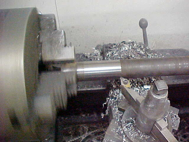
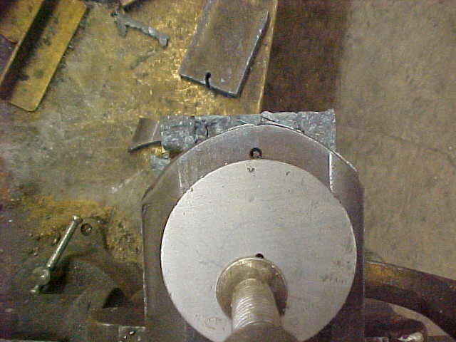
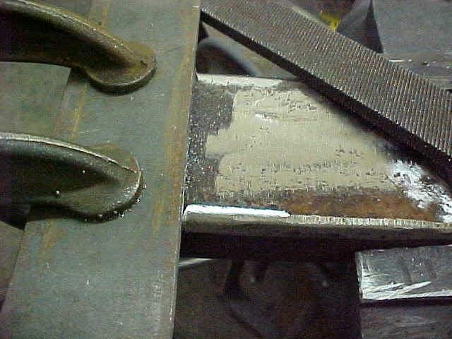
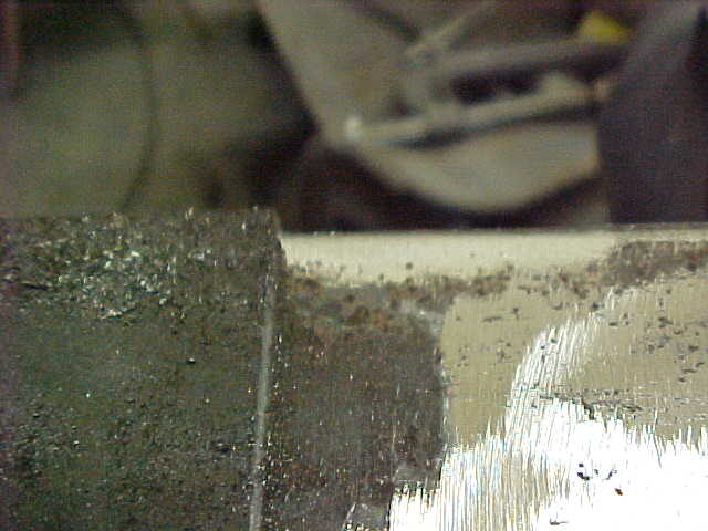
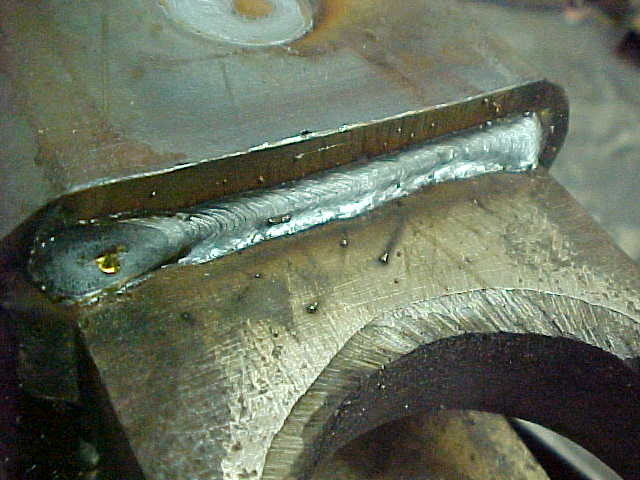
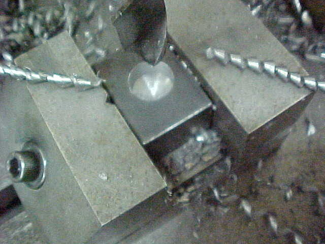
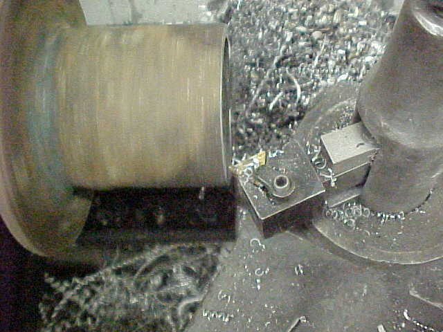
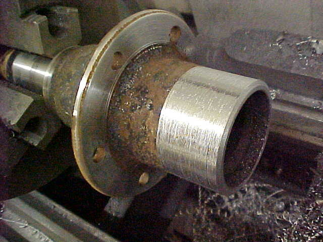
Drilled a center in the end of the shaft and spun it down to the size of the triple wall pipe. Gave it .002 - .003 clearance. Someone needs to clean their lathe!

MVC-004S_3.JPG


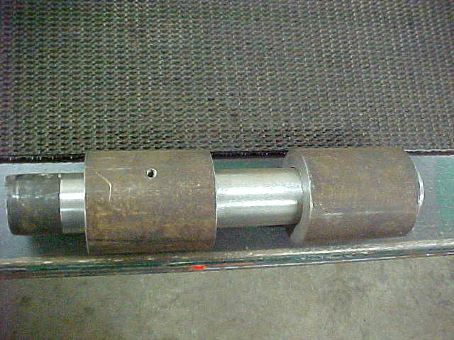
Nice and smooth and I'll cut the shaft later for the 2 sides. I'm using the same size box tubing on the spindle side and that is next.

MVC-005S_2.JPG


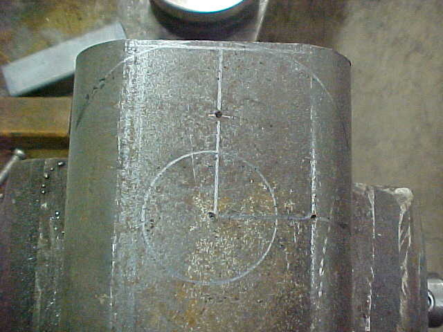
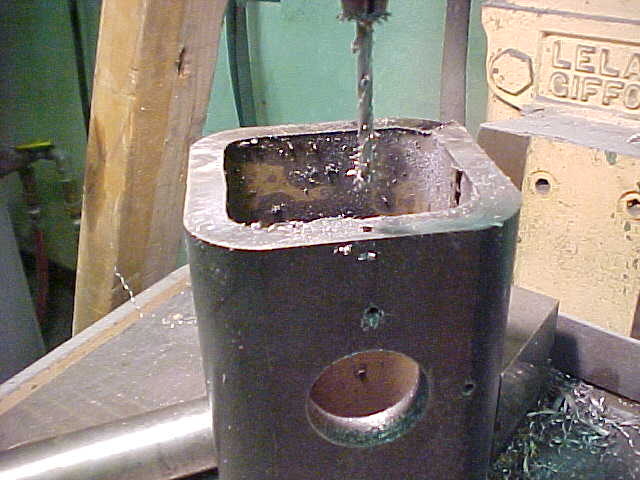
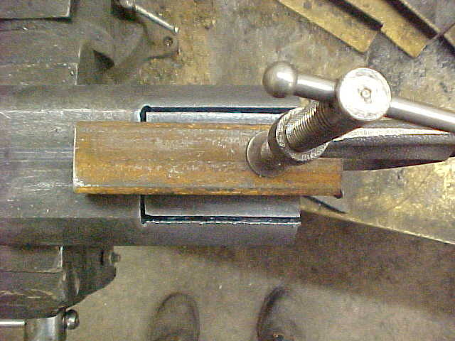
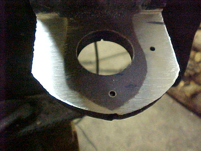
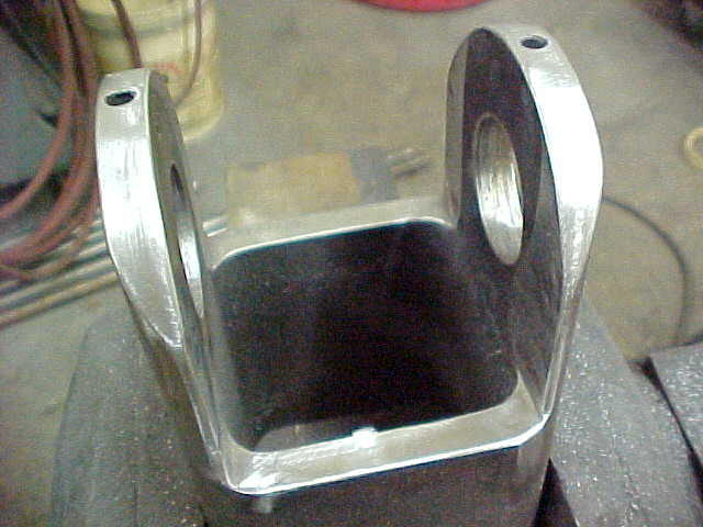
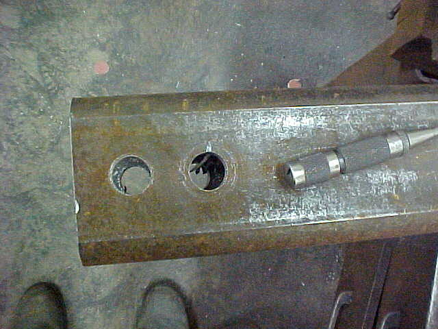
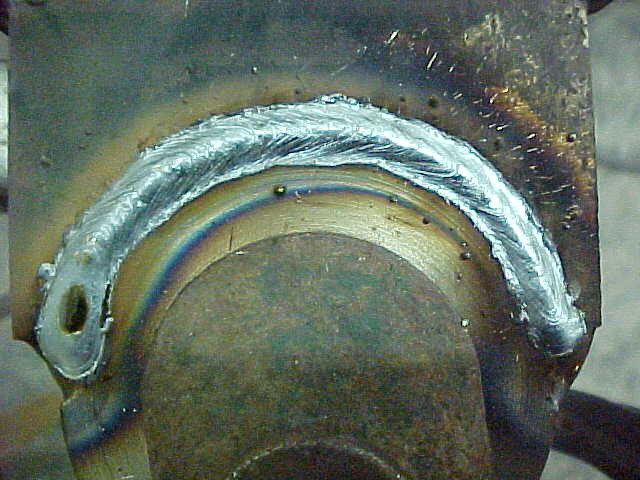
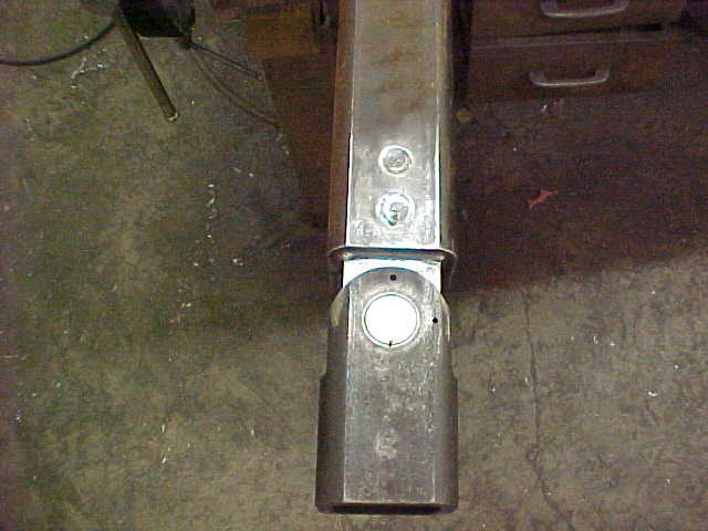
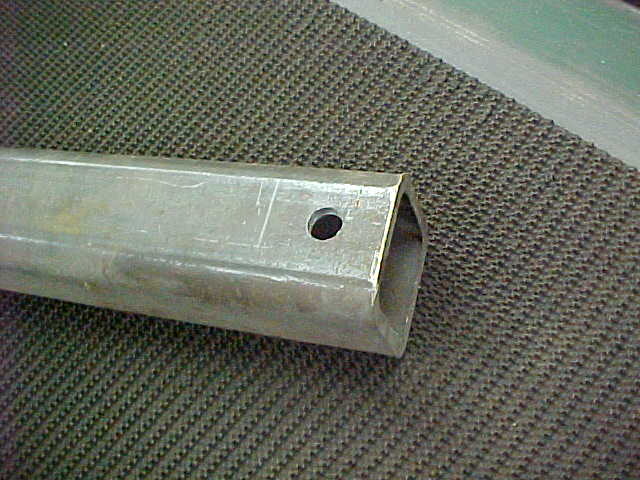
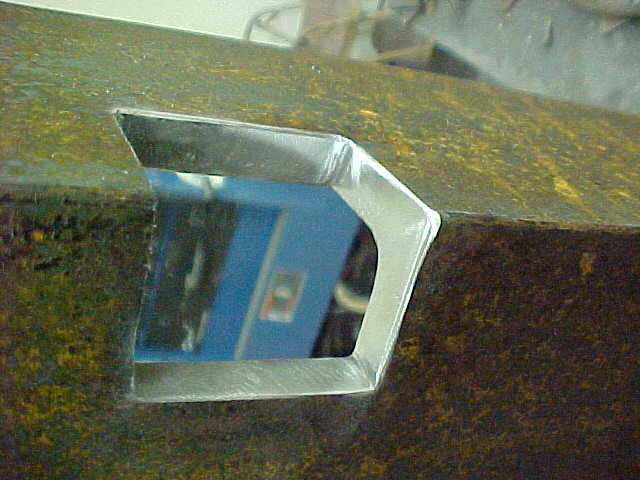
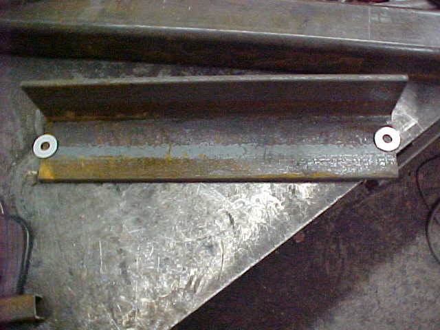
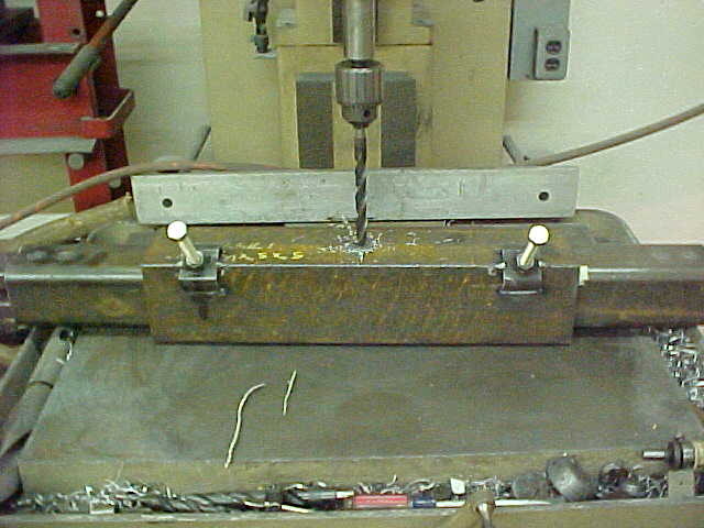
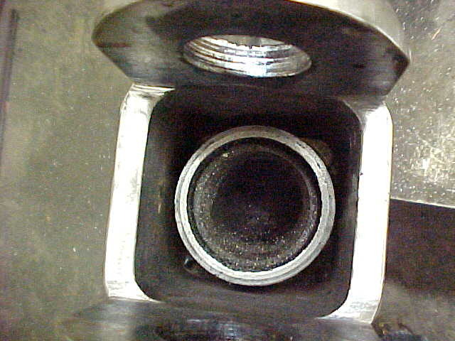
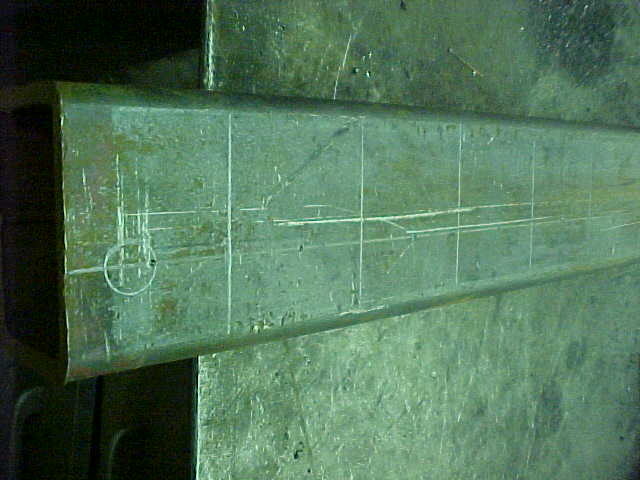
This is the 4 inch box tubing with the layout shown. 1 1/2" hole for hinge and the 2 center punched dimples will be where the locating pin will be( 0 and 90 degrees) Also going to drill the ends for set screws to hold the hinge pin in place.

MVC-006S_2.JPG


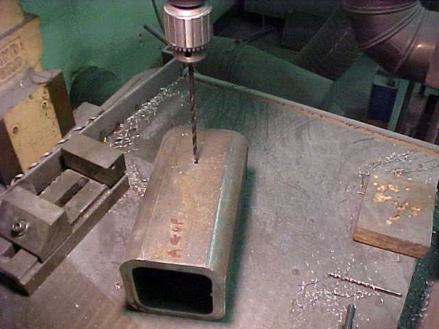
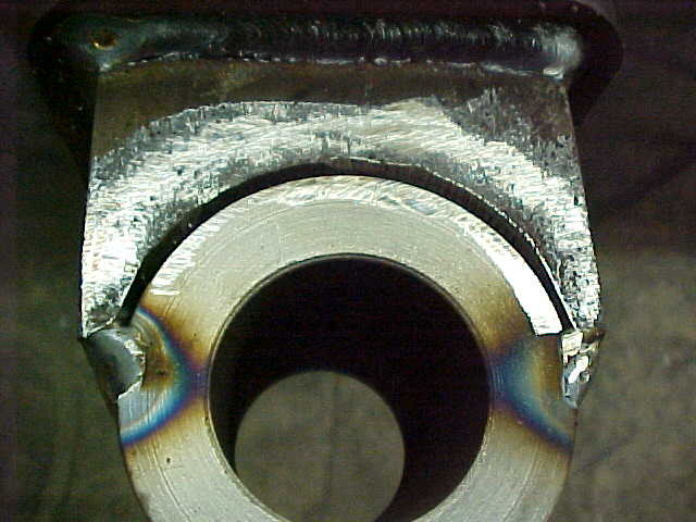
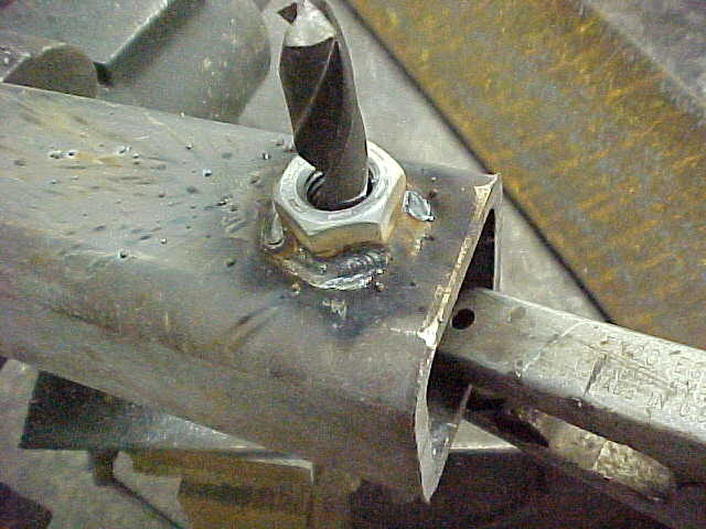
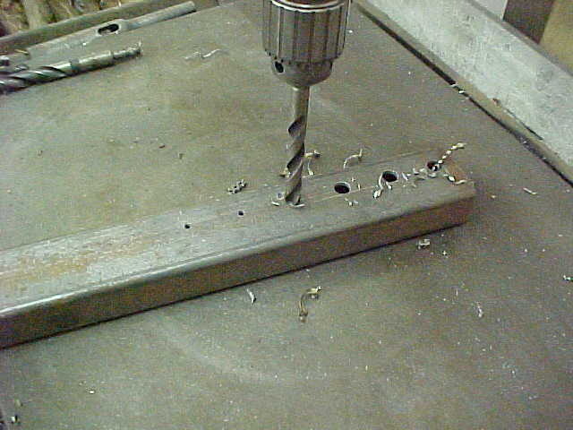
Drilled the big hole with a short pilot drill first. then switch to a longer aircraft drill to get the other side. This way the holes will be true and no more measuring needed.

MVC-007S_1.JPG


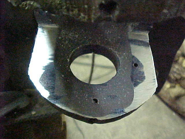
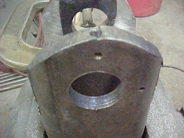
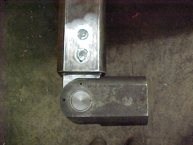
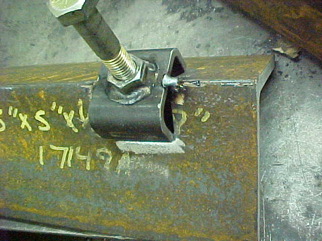
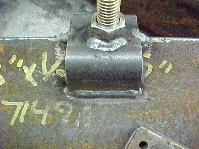
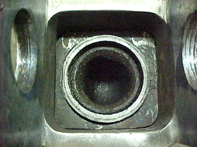
Didn't have a 1 1/2" drill or reamer so I used a hole saw again. Not real critical as the set screws will keep the shaft in position. Wear will be in the middle where it is right. Pilot drilled for set screws and drilled to tapping size. Put the shaft in and sunk it into it as well.

MVC-008S_1.JPG


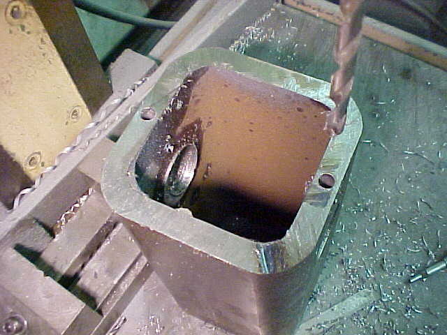
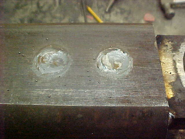
I then cobored the holes so I didn't have to tap so much. No need for that much thread anyway. The indexing holes will be enlarged when it get put together. that way I can stair step drill them so the holes align correctly.

MVC-002S_4.JPG


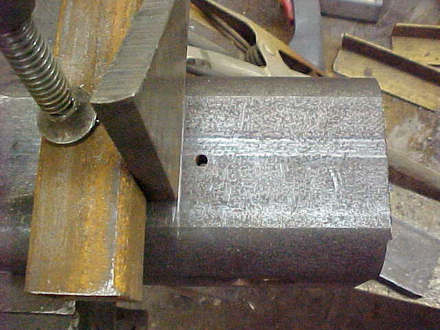
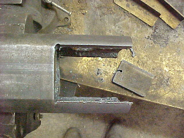
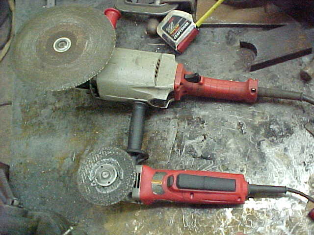
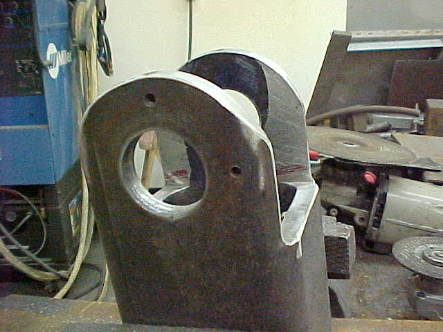
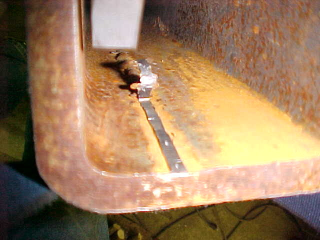
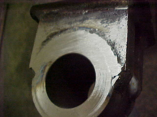
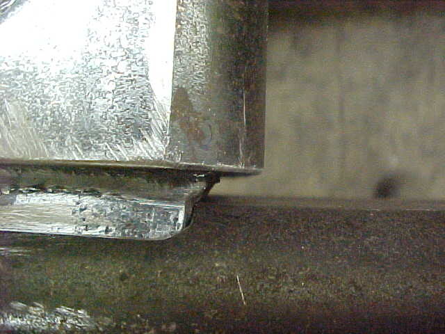
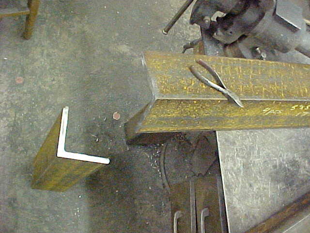
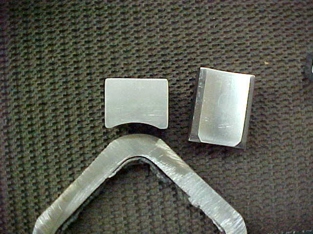
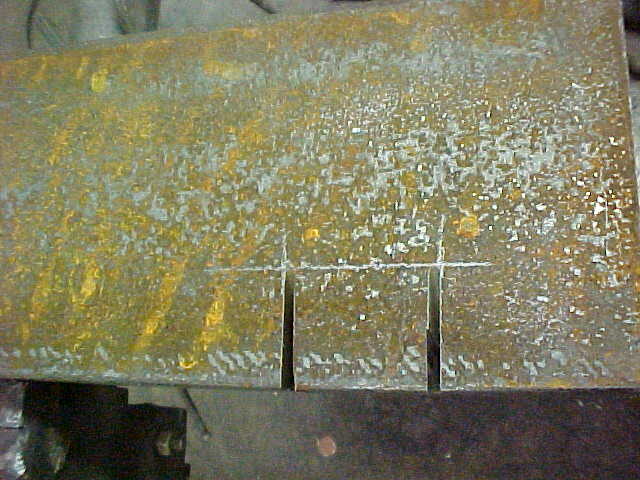
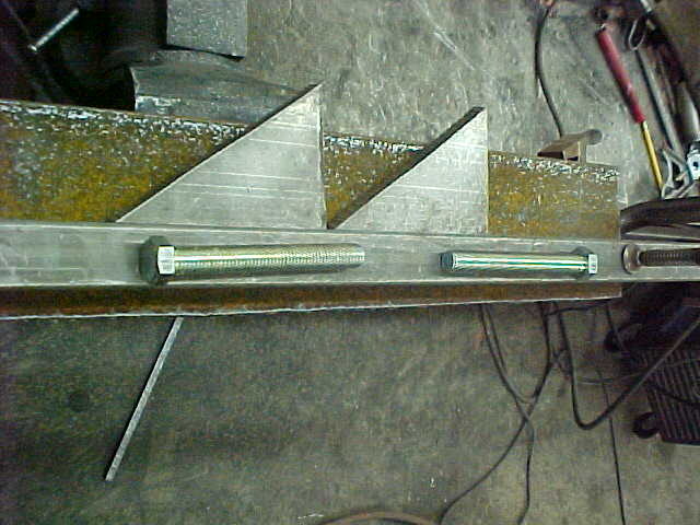
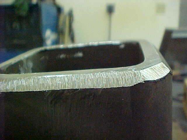
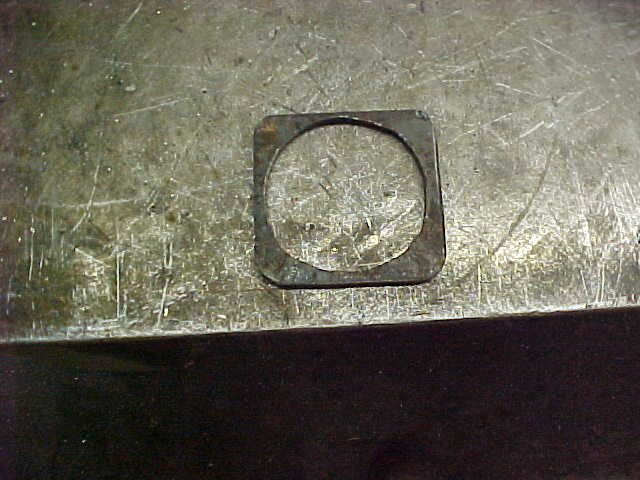
I have to cut the reliefs on the sides and going to rough them in with the plasma cutter. IF I had a mill it would be easier but I'm going to have some handwork here. Set up cheater with a 1/2 inch offset. I drill a hole to save backsplash on start up.

MVC-003S_4.JPG


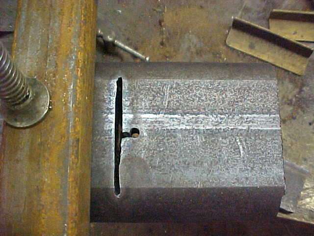
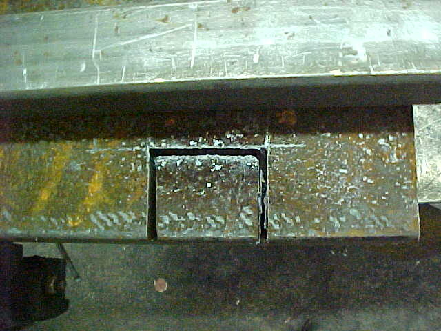
Doesn't take long at all and now I have a stop line when coming in from the end to finish the rough in for the pocket.

MVC-004S_4.JPG


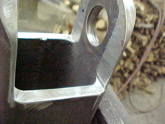
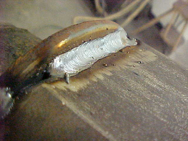
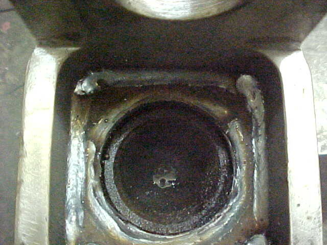
Worked out that the tubing was close enough to do both sides
You are one hell of a good fabricator.
 
MVC-005S_3.JPG


Majority is out and now I'll have some "quality" time with the angle grinders and files.

MVC-006S_3.JPG


Contoured the ends while I had the torch out.

MVC-007S_2.JPG


I spray a little dyechem or paint to get a shadow to blend too. Magic marker will work as well. This is after getting it close with the grinders and ran a file over it a few times. Takes some time but the results are worth it

MVC-008S_2.JPG


Here it is finished blended. Notice how it fades evenly to the hole side. The opposite side will ride nice on that.\

MVC-002S_5.JPG


Up next is to get the ends uniform and smooth.

MVC-001S_6.JPG


I use a piece of round as a guide and use a C cl;amp to hold it in place. Rough it real close with a body grinder, then true it with a hand file and finish with 80 grit sandpaper on a soft back pad on a die grinder.

MVC-003S_5.JPG


I guess I should show some of the tools. I keep a variety of hand files with varying cuts.

MVC-004S_5.JPG


I use a 9 inch and 4 1/2 inch angle grinders. Both are Milwaukee and I've wore out both as these are replacements. Yes, I use them a lot! With a new wheel on the 9 inch you can use it to get things real flat.

MVC-005S_4.JPG


This is a die grinder with a 3M roloc attachment. Then a 3M soft back pad. These things are great and I don't know why 3M doesn't promote them more. Sticky back sandpaper is used on them.
 
MVC-006S_4.JPG


Here's a close up of it. I like it as I can go cheap with a sand paper. I have a buddy who works at a body shop and he saves all their DA paper. Most the time they use just the outer edges and the center is fine. Not a big deal to cut them out as the pad twists off in a 1/4 turn.

MVC-007S_3.JPG


They work extremely well on smoothing thins out once you have them roughed in.

MVC-008S_3.JPG


This one is a little chewed up but wanted to show the surface. You can dress them smaller on a belt sander or bench grinder. Wish they made them in bigger sizes.

MVC-009S_1.JPG


Here is the result of using these tools. Gives stuff a better than factory finish and looks great when painted.

MVC-010S_2.JPG


The index holes will get redrilled when I get the center tube mount done.

MVC-011S_2.JPG


I made the hinge a pretty tight fit so I had to have hard corners there. I filed them in.

MVC-012S_2.JPG


For the center tube I have to weld the spindle collars inside and it needs to be smooth. The weld slag is in there and I used a cold chisel to get most of it out.

MVC-013S_2.JPG


On the spindle tube holders I had to radius the outer edges to match the inside of the tube. Did it quick with the angle grinder but wanted nice , sharp corners to hold itself in place and allow it to be checked for the correct position.

MVC-014S_2.JPG


Marked the line and clamped a piece of steel on the line. Then hand filed it. Here it is finished.
 
Great work. It's always so sweet when one has the equipment to do the job. I am so envious. What you're doing is my absolutely funnest thing to do. But all that is in the past. I do enjoy your builds.
 
MVC-001S_5.JPG


Drilled 4 large holes down the length. These will be so I can plug weld the spindle/hinge tubes. Hard to get a lot of good weld on the inside so this will work in this application.

MVC-002S_6.JPG


Crank the amps up and try to push the heat down, then circle your way up to fill. Makes it basically flush when complete.

MVC-003S_6.JPG


Then welded the front side. Snag ground reliefs on this stuff for stronger joints.

MVC-017S_2.JPG


I chamfered the tubes as I want some extra there. I have to grind it flush after welding as the other half rides on it. Cleaned everything for welding.

MVC-018S_2.JPG


Clamped a piece over the hole to keep it clean and put a bead down.

MVC-019S_1.JPG


Ground down and filed in.

MVC-020S_1.JPG


All done except the index holes and works great.

MVC-021S_1.JPG


On 90 degrees it bottoms out on the center tube as I had hoped it would.

MVC-022S_1.JPG


Couldn't have anymore room than that! I relieved the steel in most places prior to welding so it's even stronger than it looks.
 
MVC-001S_7.JPG


Next is to make a box that with hold the axle. I also need to have it "lock" into position for road transport and have something to keep the slop out of it. I cut 2 pieces of angle to length.

MVC-002S_7.JPG


I'm going to make pushers out of some 2 1/2" box beam. 3/8" thick so it will be strong enough. Drilled the 5/8" tapping size hole through. I'll cut it in half to make the 2 brackets.

MVC-003S_7.JPG


Cut a couple chunks of solid steel out and ground a 1.05 inch radius to match the box beam on the axle. This will push the axle on 45 degrees making a positive locking system.

MVC-004S_6.JPG


Here's a trick. When you want to weld a nut on and tap the beam below. Run your old drill up through the tube and nut. This will self center it so you can tap easily. I've had binding issues when tapping the beam prior.

MVC-005S_5.JPG


I countersunk the blocks with a 5/8" hole. This will keep it in position while the tube is sliding.

MVC-006S_5.JPG


Back to the angle. Marked where I wanted the brackets to be welded and cut to the lines with a small wheel on the chop saw.

MVC-007S_4.JPG


Then cut the straights with the plasma cutter.

MVC-001S_8.JPG


Cleaned up the pockets and ready to weld the pusher brackets on.

MVC-002S_8.JPG


After double checking and cleaning up the edges for good welding contact I tacked them on. Everything looked good.
 
Nice build. Nice photos - thanks.

I used the 3M soft backed pads for smoothing ('fairing') boat hulls. They also sell some through their auto body finishing line.

I have also made up a few by gluing different densities of foam to backing pads, including on a larger (7") disc sander.

Philbert
 
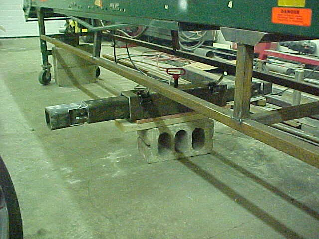
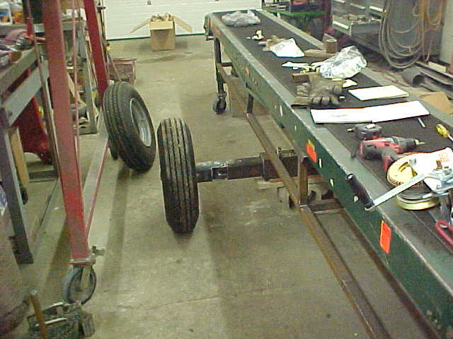
I'm not entirely sure where you are going with the design. Post #26: Will spindles be welded on these to rotate the wheel/tires 90 degrees rather than a straight axle? Very nice option if so.

Yeah, that's the plan on the axle. Basically be able to slide the axle completely to one side to pull right up next to it. Or if your splitting into a truck or pile, Turn the wheels 90 degrees and move it sideways in a radius fashion without having to move the truck or trailer or your splitters position. You could also move it the same if you are just pilling a lot on the ground. Just wanted options while I was making it. I like to play!:yes:

It will come to light in future pics.. at least I hope it works!
 
MVC-003S_8.JPG


Final welded them and should be plenty strong. I'd like to double nut them but will either have to find an extra long threaded bolt or modify the ones I have here.

MVC-004S_7.JPG


Now I'm ready to get the outer box ready to weld. I'll use some .155 thick washers so I have even slop and the tube will slide easy. This will allow fot any warping during welding too.

MVC-003S_9.JPG


Went to the surplus store and low and behold they had these 5/8 bolts with threads all the way at a $1.00 a pound. I'll cut them to size later. I cut the angle here on 2 sides to get the gaps right for welding.

MVC-004S_8.JPG


With the box tube inside along with the washers I then stitch welded it all up.

MVC-005S_6.JPG


Tightened the bolts down and then drilled a 3/4" hole for the pin. It will be a safety to keep the axle from being able to move side to side while in transport.

MVC-006S_6.JPG


Slid it under for mock up and looks good.

MVC-007S_5.JPG


Slid a tire and spindle in to have a look see. I'm keeping a 6 ft wide track so it doesn't take up a lot of road while moving. Up next it to weld the spindles to the outer hinge box.

MVC-008S_4.JPG


My BIL cut the spindles off quick and wanted to true them up so I took them apart and ran them on the lathe.

MVC-009S_2.JPG


While it was in there I skimmed the flange face and cut the tube to a nominal size. You'll see why shortly.
 
MVC-010S_3.JPG


Angle ground the box heavy for a strong joint and cleaned up the flats for welding.

MVC-011S_3.JPG


Laid the first bead down.

MVC-013S_3.JPG


Then put a second bead all the way around. Up next is to weld the backside on the inside of the tube.

MVC-014S_3.JPG


This is what I have looking inside. Going to make up a filler piece that will take the gaps in so I can weld it all up here as well.

MVC-015S_2.JPG


Got some 1/4" x 3 strap and cut it out with a hole saw while it was long. Rounded the 2 corners then cut it off. I then rounded the 2 remaining corners. The hole saw was a nominal size and that is why I turned the shaft down to that size.

MVC-016S_2.JPG


Drove the filler in and now it is ready.

MVC-001S_9.JPG


All welded and done now.

MVC-002S_9.JPG


Now I'm going to make the brackets for the support/lift arms. Using box tubing here and will drill all the holes first. It's easier to hold for me that way and it's keeps them straight with no flexing while drilling.

MVC-003S_10.JPG


Did the measurements and allowed for the cut as well. No bandsaw so I'll use the chop saw for that.
 
Kevin I own all miller except for a old lincoln arc, what do you own? Would love to see some pics of your tools too. My two good buddies have hobart welders and a "snap-on" The scrap-on never seems to feed the line right.
 
Kevin I own all miller except for a old lincoln arc, what do you own? Would love to see some pics of your tools too. My two good buddies have hobart welders and a "snap-on" The scrap-on never seems to feed the line right.

They are in some of the pics if you look in the background. Miller 250X MIG, Miller Syncrowave 250 and Hypertherm plasma.

Has your buddy replaced the liner on the Snap-on? That's the number one cause on feed issues. Dust/dirt over time builds up on the wire spool in the machine and that dust gets fed into the line. After a while it puts too much friction that the drive rollers can't push it smoothly causing it to either slip or chug if you will. I've replaced mine about 4 times over the years. The covers are FAR from air tight and dust gets in there. When I'm not using mine I now put a blanket inside to keep the dust from building up on the wire.
 
Very nice build - all looks heavy duty. With all the fabrication you are doing, it seems like you could have just as easily started from scratch, instead of using the Kmart conveyor!

Philbert

Have you priced belts, bearings and rollers? Just kidding. I'll let them figure all that out plus I have gear reduction, motor and electrics all in place. It's a good quality piece.
 
Looking at @Sandhill Crane conveyor and his mobility coment, think maybe mounting one above a old garden tractor so moving it and powering it could be easier. Maybe a old wheel horse with its pto powering the conveyor..........
 
They are in some of the pics if you look in the background. Miller 250X MIG, Miller Syncrowave 250 and Hypertherm plasma.

Has your buddy replaced the liner on the Snap-on? That's the number one cause on feed issues. Dust/dirt over time builds up on the wire spool in the machine and that dust gets fed into the line. After a while it puts too much friction that the drive rollers can't push it smoothly causing it to either slip or chug if you will. I've replaced mine about 4 times over the years. The covers are FAR from air tight and dust gets in there. When I'm not using mine I now put a blanket inside to keep the dust from building up on the wire.

I picked up a pack of filters for my might wire from my local welding shop. It really cuts down on the cap that gets dragged into the liner. I also cut up a 3m pad and stacked it like an accordion before the filter. I figured it would "scrub" the wire before it runs through the fine filter.
 
Back
Top