Conveyor build

Arborist Forum

Help Support Arborist Forum:

This site may earn a commission from merchant affiliate links, including eBay, Amazon, and others.

Kevin in Ohio

Addicted to ArboristSite
AS Supporting Member.
Joined
Jan 2, 2009
Messages
1,844
Reaction score
2,371
Location
Ohio Stop Jawin' and start Sawin'
Okay, people seem to like build threads and I got a lot of favorable comments from the splitter so I'm going to do one on this conveyor. WARNING, this will be a step by step with lots of pics and descriptions so some my not like the detail. I always like stuff like this because I can pick up tricks and ideas for future projects. Not saying the way I do things is the best way, It's just the way I did it and Lord knows I make some mistakes along the way.

With the disclaimer out of the way, ;) here's the plan. Always try to come up with something to make the wood gathering/processing easier. I take the approach of using the money saved to make the "system" easier. This also lets me be able to do wood heat longer as age creeps up on me.

Been watching sale adds and such for a conveyor. My plan was to get a conveyor with options. I want to be able to use it as not only a conveyor but also a level, moving table that is totally adjustable. I have some ideas I have not seen on current offerings so some of it may be a little involved or may not work at all. All part of the fun huh? Here we go.

MVC-010S.JPG


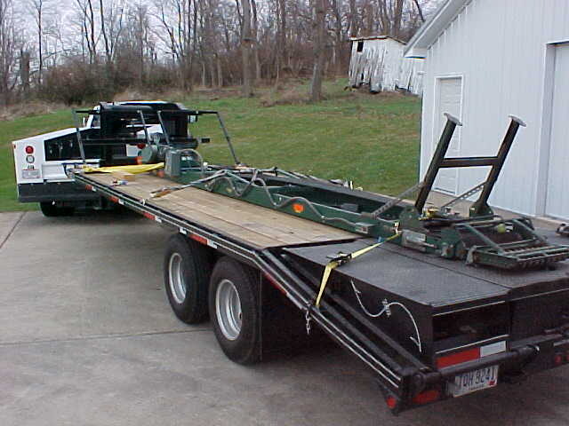
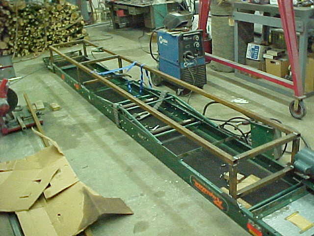
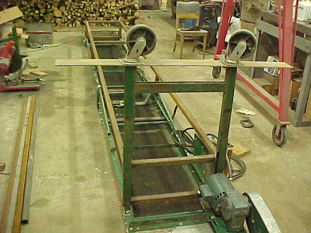
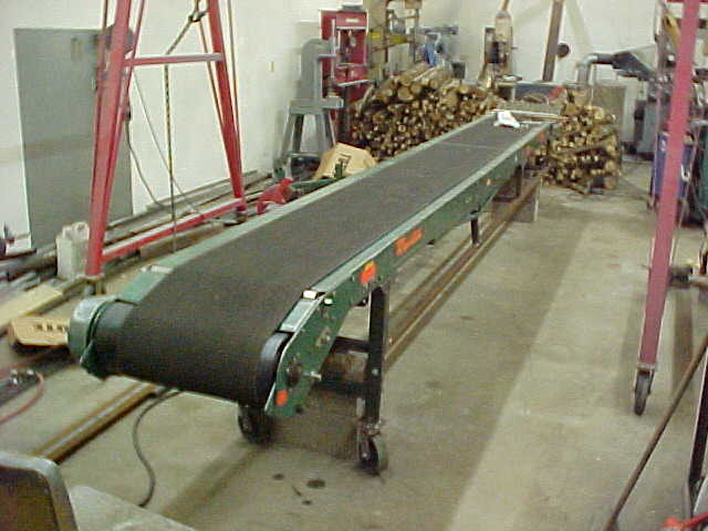
Got this conveyor off craigslist and it was listed by the manager of a closing Kmart store. It's 20 foot long and has a 2 ft wide with a 18 inch wide belt.

MVC-011S.JPG


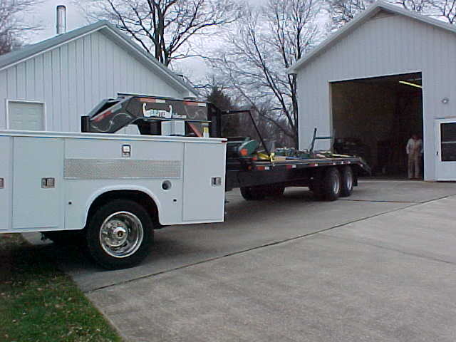
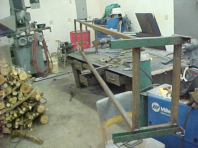
Just home here and backing it in to the shop. Luckily they loaded it with their forklift and helped getting it down to the floor. WE took rollers along to roll out then he again lifted it onto the trailer. Sure made it easy and glad they were so helpful.

MVC-012S.JPG


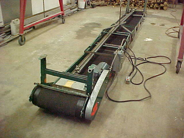
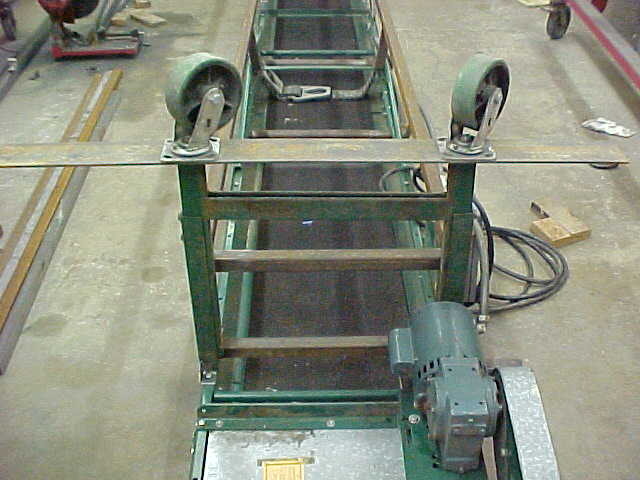
They were using it to feed their storage loft and I bet many a box went up there. It has a 3/4 horse single phase motor with gear reduction.

MVC-013S.JPG


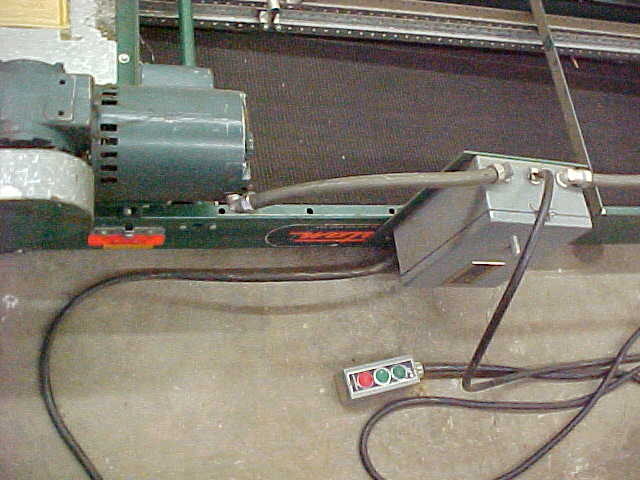
A great feature it has is forward and reverse. I'll be using this flat a lot to load and unload but want to see how it will do loading into a trailer. No paddles or hooks will limit the steepness it can go but the belt is pretty rough and "grippy" so we'll see.

MVC-014S.JPG


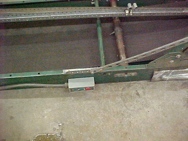
It has switches at top and bottom which is great as well. Outside out of reach of an outlet I'll have to take a generator along but it won't be a problem for me. Being able to switch on and off and reverse directions more than makes up for it.

MVC-015S.JPG


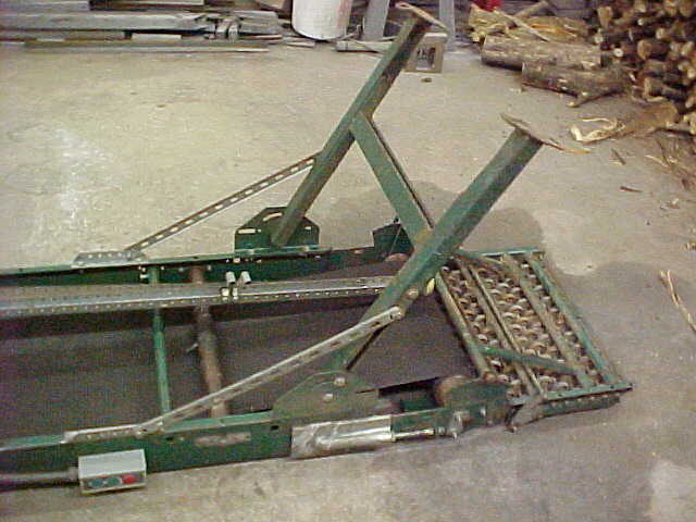
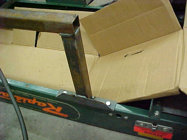
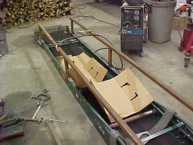
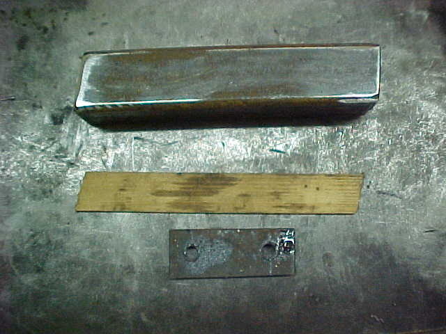
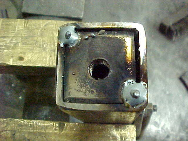
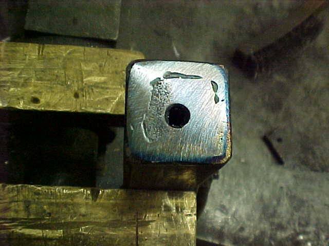
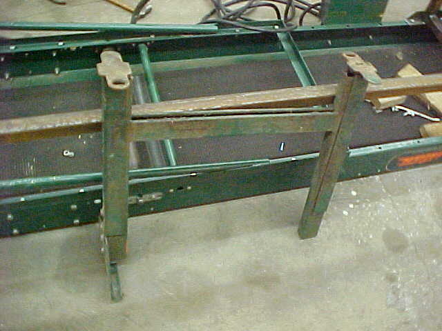
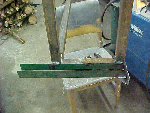
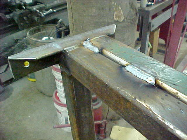
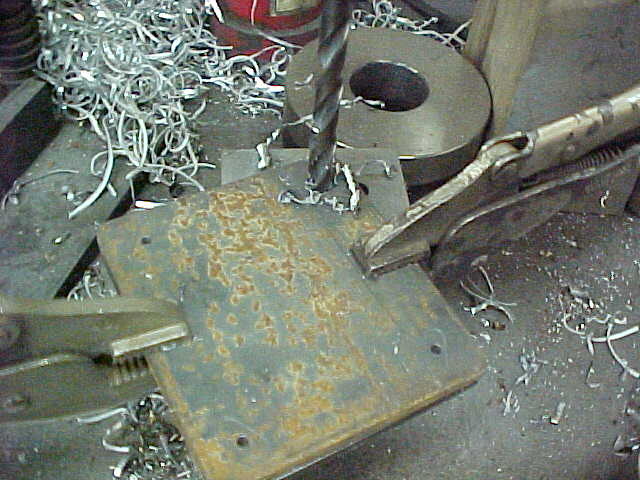
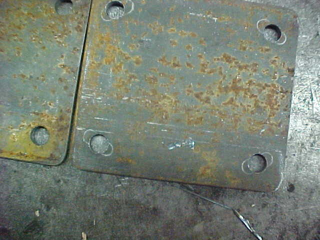
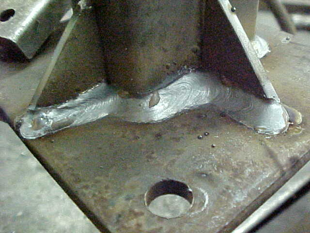
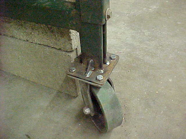
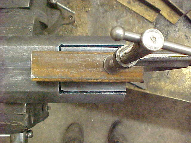
My idea is to make a straight substructure so I can have a slide rollers to raise and lower it like a hay elevator. First step is to take off the feet that are on it.m It's all bolted on so it will be easy.

MVC-016S.JPG


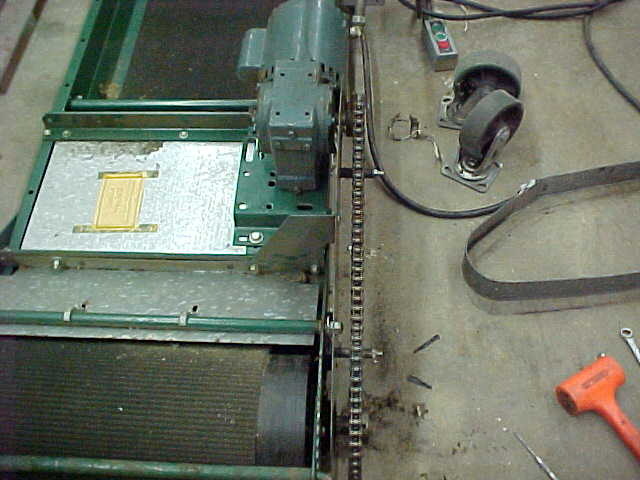
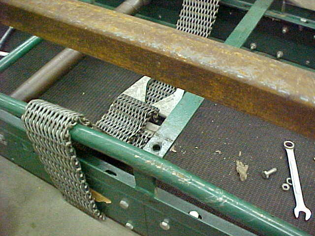
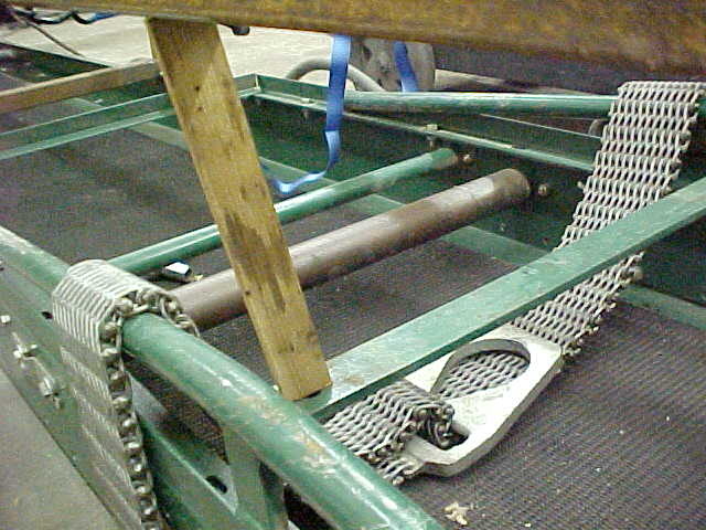
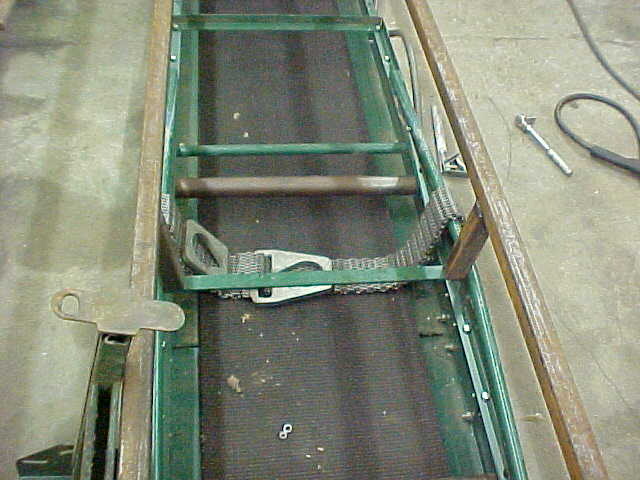
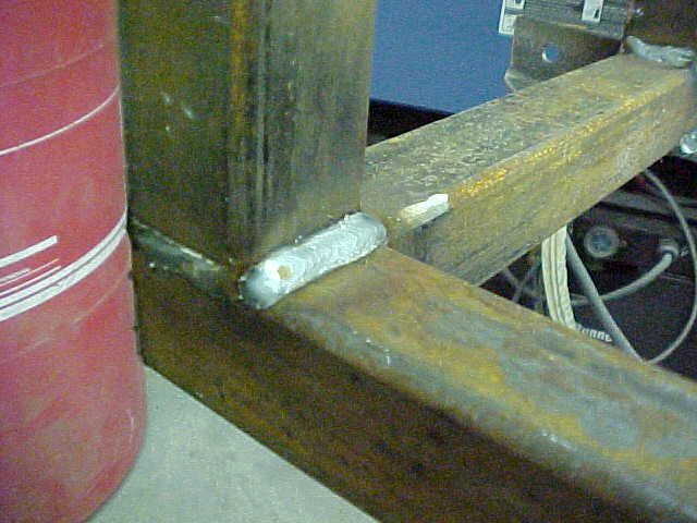
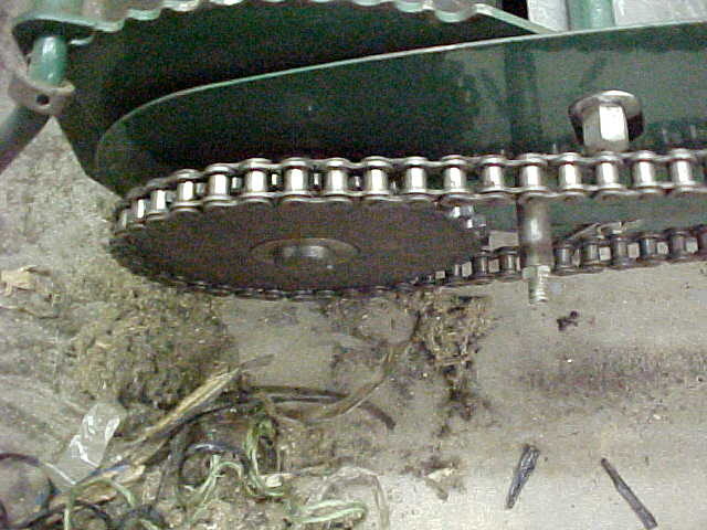
Took the cover off and got a surprise. Twine , plastic and tape was wrapped around the shaft. Then I notice something else. See how the chain is straight?

MVC-017S.JPG


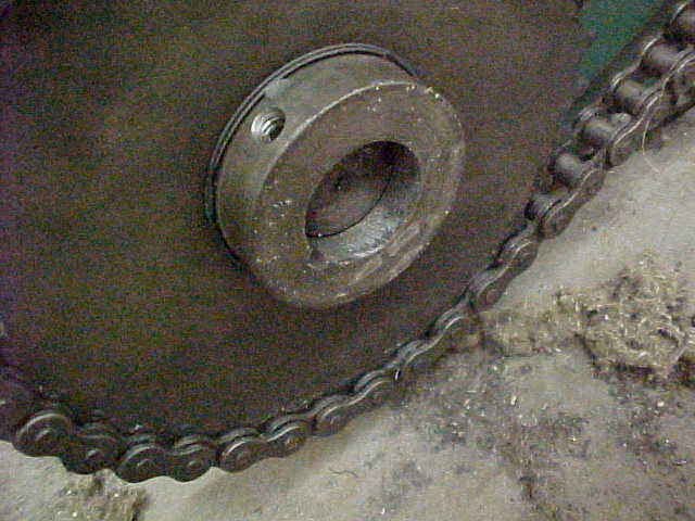
Either someone at the factory or whoever assembled this put the gear on backward. Notice the set screw can't even be tightened as it's on 2/3 on the shaft.It was loose and the only thing from keeping it on was the binding of the chain.

MVC-018S.JPG


I think they did it because you have to have a long allen wrench to get in there if you put it on right. Notice all the stuff that was wrapped up in it on the floor.
 
MVC-019S.JPG


Using Box tubing for the substructure and needed to lengthen the pieces I had. Cleaned them up and put a chamfer so good weld build and strength.

MVC-020S.JPG


Makes for a good weld and I'll hit all sides.

MVC-021S.JPG


Made up some brackets to bolt it all on. I don't want to weld it on as I can change stuff that way. Rails have holes allready in it so it's a no brainer.

MVC-022S.JPG


Welded the ends on at the table then bolted the brackets on and brought the rail over. I then tacked the rail to the brackets. Takes all the measuring out of it and saves mistakes. I put cardbord over the belt to save it from the sparks and such.

MVC-023S.JPG


The rails are this tall to get over the motor and gearbox on the other end. They also have a stretcher in the middle and want to leave that on.

MVC-001S.JPG


Up next are the cross members that will give it strength and will keep everything square. I'm using a chop saw for the majority of this.

MVC-002S.JPG


Tacked them all in and kept checking squareness. Everything came together nice.

MVC-003S.JPG


The center has this tube brace and I want to leave it in. The easiest thing I can think up is an angle tube coming from the cross brace. Not much support under it but I think it'll be fine. Time will tell.

MVC-004S.JPG


Easiest way I have found is to use a paint stick for a pattern. Trim the angles till their right and the length as well. Takes a little time but saves mistakes and wasted metal.
 
Just heard about one here in Michigan the other day but forgot to call about it. I built a firewood conveyor out of a 15' long sheet bent 90° along the length, used some old 60h. chain with 4" dogs welded every 2'. Ran it off a secondary circuit on splitter
 
I loved the wood splitter you built, great job. I'm looking forward to seeing how this turns out.

P.S. rapistan conveyors are very good, I've had several of them when I was at a garden hose factory. I was a maint. mech. there and those conveyors just like yours gave great service 24 hours a day 5 to 6 days a week with almost no problems. There was three folks winding garden hoses about one every thirty seconds and slamming them down on the deck. That should see less of a duty cycle in firewood service.
 
Man, Kevin I like you builds, always lots of pics and explanations. My son and I were just talking about trying to rig a conveyor to fill the wood shed last weekend. He is twelve, but darn the kid has lots of good ideas. I think he want to be an engineer, but he used to want to drive the garbage truck not long ago. Think he is just tired of dad working him like a rented mule.

Good job Kevin keep it coming.
 
MVC-005S.JPG


Going to run a bolt up from the bottom to secure it. Got a piece of scrap 3/8" metal and marked the center and in measure of the hole. Centered it and pilot drill.

MVC-006S.JPG


Drill the hole to tap size

MVC-007S.JPG


Then put a tap in and start it. I keep them loose and then finish by hand.

MVC-008S.JPG


All tapped and tube cut to size. Now I'll cut the tapped plug to size.

MVC-009S.JPG


Beveled the edges and set it flush, Tacked it in place.

MVC-010S_1.JPG


After welding it in I ground the weld to flush.

MVC-011S_1.JPG


Both of them done and in and gives a pretty clean look.

MVC-012S_1.JPG


On the end I want to have heavy caster wheels so when loading/unloading on the level it doesn't get tippy and it will be self contained. I'm going to reuse the foot bracket as it has adjustment capability.

MVC-013S_1.JPG


I cut the feet off and will be mounting it backwards from what they had. Just works out better for my application. Welding it on here.
 
MVC-014S_1.JPG


Both of them on and doing all the final welding.

MVC-015S_1.JPG


With the box tubing you can get pretty strong joints because of the surface area.

MVC-016S_1.JPG


Frame work serves double duty to strengthen the whole thing and give me a nice track for the lift wheels to follow.

MVC-017S_1.JPG


Bolted it all back on and the highest the wheels will be is 54 inches.

MVC-018S_1.JPG


The lowest is 36 inches which is about as low as I want to reach. I like this system as I can take the adjustable section out if I want to use it as an elevator or go into a trailer.

MVC-001S_1.JPG


Cut the mounting plates out with the chop saw, rounded the corners and smoothed the edges

MVC-002S_1.JPG


Laid the caster on and traced the holes. center punched and pilot drilled and then drilled the final hole size. Notice I clamped both of them together for time savings.

MVC-003S_1.JPG


All done and ready to weld onto the legs.

MVC-004S_1.JPG


Remember the brackets that attached the box beam rails to the conveyor? I cut 45's on the edges and these are the scraps. Now to use them for strengthening gussets.
 
I assume this conveyor is to load the split wood coming from the splitter. Not to manage the wood going to the splitter.

tappa talk samsung note 2

As of right now, no. We split everything where it falls. back the splitter down the trunk, throw to the sides, back the truck down the same path and load from both sides. just the way that works the best for us. Right now the plan it's main use will be to load/unload out of the barns and furnace house to save another handling and steps. One guy in the truck feeding the conveyor table(laying flat) and the other stacking. Or, if I'm by myself I can load the whole conveyor by stop and start. Then walk in and unload, start and stop. Some of the barns we stack in get hard to stack when your doing the center sections so I think this will speed things up.

I'm making it so it CAN be used for whatever may come up because sometimes situations change. I like to have options!
 
MVC-005S_1.JPG


Tacked the brackets on and rechecked them for straightness. Then put the gussets on and welded everything up.

MVC-006S_1.JPG


Makes for a nice strong mounting base.

MVC-002S_2.JPG


Close up of the front leg. I'll drill a hole through both legs and put a bolt in for now. probably put a pin with linchpin later. Single bolt you see here is one of 2 pinch bolts that Have slide inside. Not strong enough to hold it for me.

MVC-001S_2.JPG


Slid the caster assembly in and rolled the conveyor back over. Starting to come together now.

MVC-004S_2.JPG


Next up is getting the wheels and lifting system worked out. First up is the axle and wheels. Brother in law came through for me and had some mobile home spindles. Even brought me 2 new rims and tires. Thanks Rod!!

MVC-001S_3.JPG


I'm doing something a little more involved than just a normal axle. I want to be able to slide it flush with the side so you can pull beside it close and have the wheels to be able to turn 90 degrees. Some idea crunching in my head and started by cutting a couple 2 1/2 inch holes in a 3/4 Inch thick strap.

MVC-002S_3.JPG


Use a lot of cutting oil and slow speed and those hole saws will last pretty good. After one was drilled I cut it in the middle and cut the rest off. Then did another one for the other side. These will be weld cradles for the outside of the hinge.

MVC-003S_2.JPG


Used some triple wall pipe I had laying around and they will be what the hinge will ride in. 2 1/2" OD 1 1/2" ID. I want this whole hinge to be able to slide in the axle tube. Hard to explain but as we go along you'll see what I'm after. Trued them up on the lathe.

MVC-001S_4.JPG


I always add grease zerks on everything so stuff will last and this is no exception. Won't get a ton of wear but it's always nice when something works easy! Easier to drill and tap before welding up so that's what I'm doing here.
 
MVC-003S_3.JPG


Drilled a center in the end of the shaft and spun it down to the size of the triple wall pipe. Gave it .002 - .003 clearance. Someone needs to clean their lathe!

MVC-004S_3.JPG


Nice and smooth and I'll cut the shaft later for the 2 sides. I'm using the same size box tubing on the spindle side and that is next.

MVC-005S_2.JPG


This is the 4 inch box tubing with the layout shown. 1 1/2" hole for hinge and the 2 center punched dimples will be where the locating pin will be( 0 and 90 degrees) Also going to drill the ends for set screws to hold the hinge pin in place.

MVC-006S_2.JPG


Drilled the big hole with a short pilot drill first. then switch to a longer aircraft drill to get the other side. This way the holes will be true and no more measuring needed.

MVC-007S_1.JPG


Didn't have a 1 1/2" drill or reamer so I used a hole saw again. Not real critical as the set screws will keep the shaft in position. Wear will be in the middle where it is right. Pilot drilled for set screws and drilled to tapping size. Put the shaft in and sunk it into it as well.

MVC-008S_1.JPG


I then cobored the holes so I didn't have to tap so much. No need for that much thread anyway. The indexing holes will be enlarged when it get put together. that way I can stair step drill them so the holes align correctly.

MVC-002S_4.JPG


I have to cut the reliefs on the sides and going to rough them in with the plasma cutter. IF I had a mill it would be easier but I'm going to have some handwork here. Set up cheater with a 1/2 inch offset. I drill a hole to save backsplash on start up.

MVC-003S_4.JPG


Doesn't take long at all and now I have a stop line when coming in from the end to finish the rough in for the pocket.

MVC-004S_4.JPG


Worked out that the tubing was close enough to do both sides
 
Looks like a great score on the conveyor! Subscribed. I read your splitter build and was blown away. I'm sure this will not disappoint either. I cant wait to see the final pics of the operation in action. Or maybe a video of the entire process. ;)
 
Back
Top