Conveyor build

Arborist Forum

Help Support Arborist Forum:

This site may earn a commission from merchant affiliate links, including eBay, Amazon, and others.
MVC-018S_3.JPG


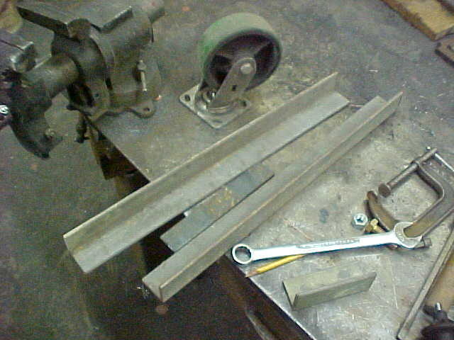
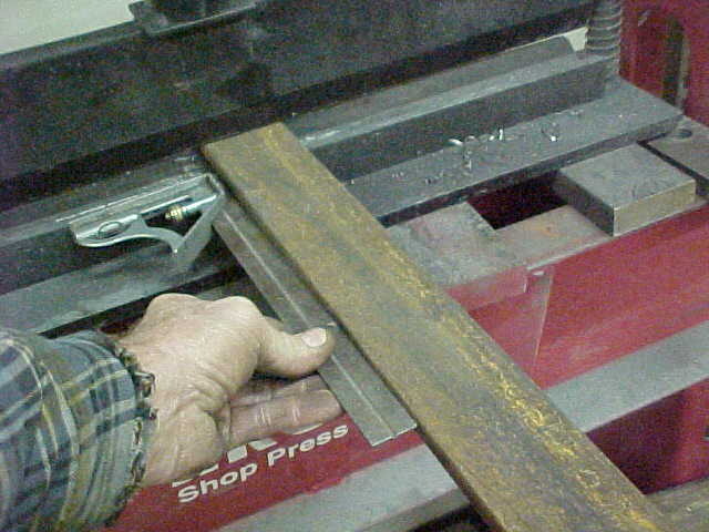
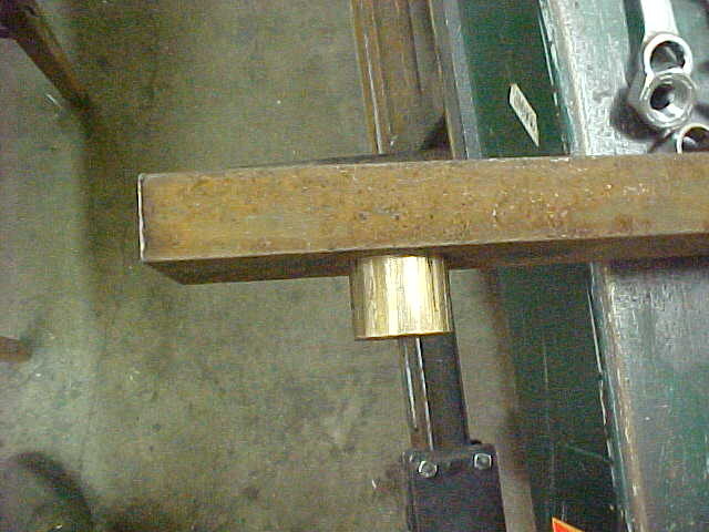
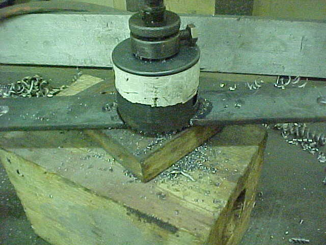
Sticking out the back side so I'll cut it off in the chop saw. and grind it all flush.

MVC-019S_2.JPG


I then drilled and tapped it for a grease zerk while it was easy to do.

MVC-020S_2.JPG


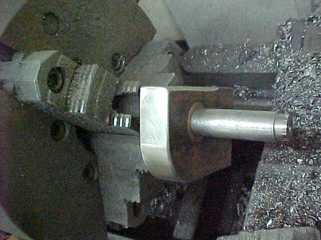
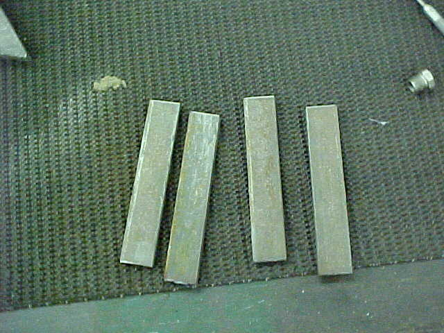
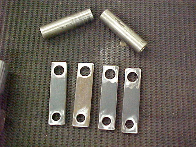
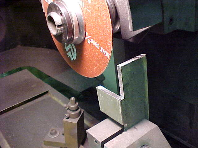
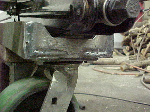
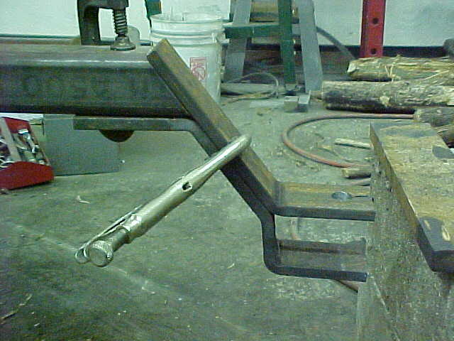
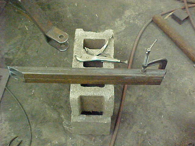
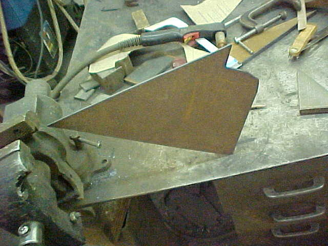
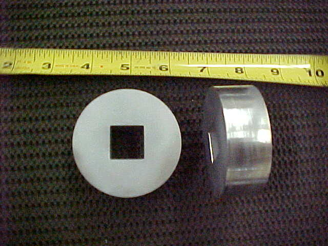
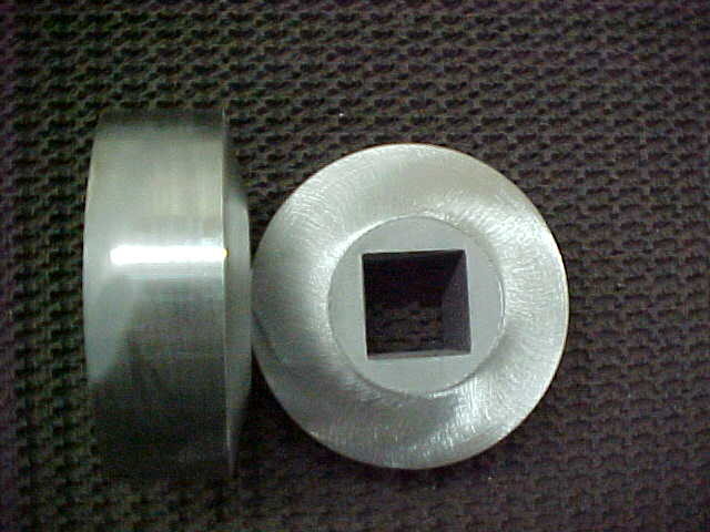
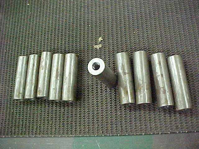
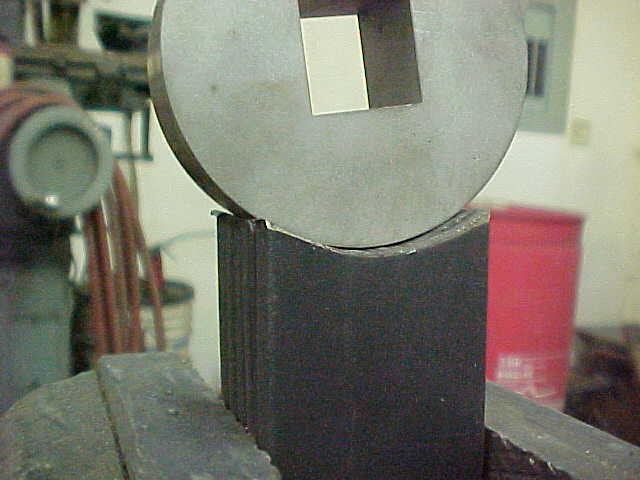
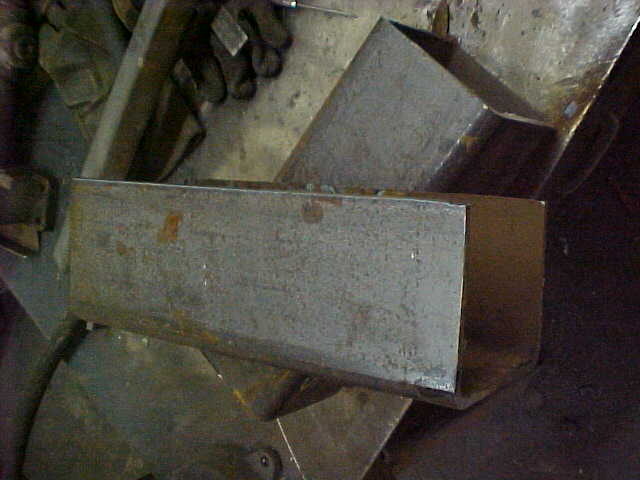
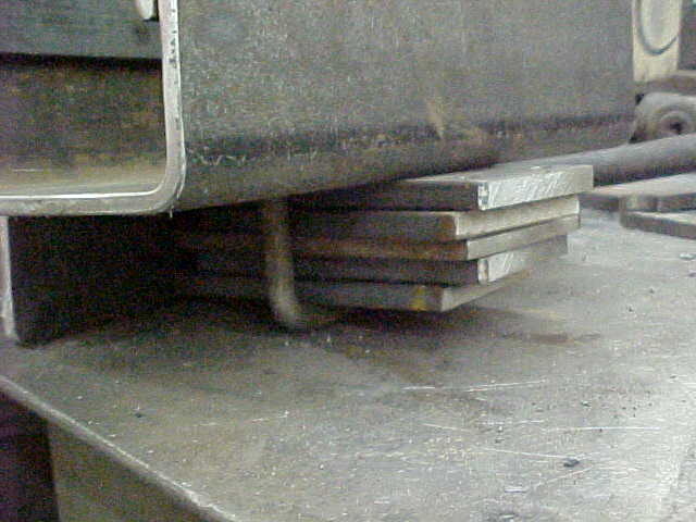
Cut the flat to 4 1/2 inches and rounded the one corner. I then got some bar stock and turned it to just fit the bushing. Test fit it here and slips on real smooth.

MVC-021S_2.JPG


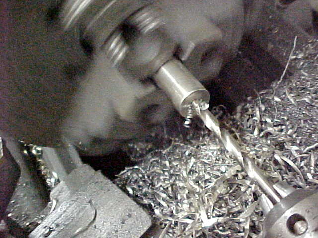
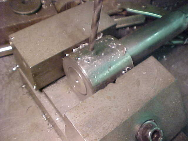
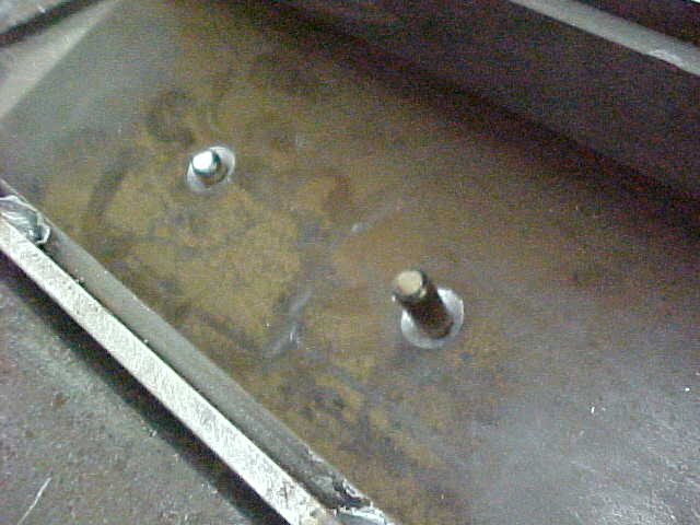
I then turned the shaft down to slip into the pipe. This way it'll self align when welding.

MVC-022S_2.JPG


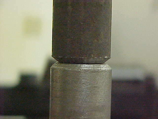
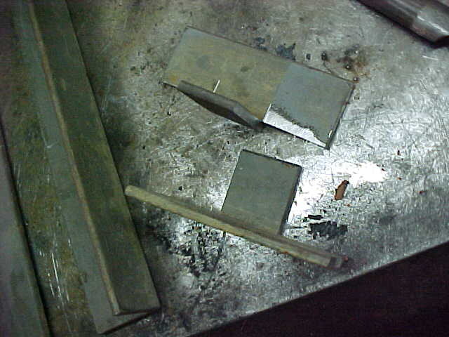
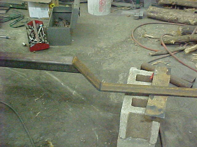
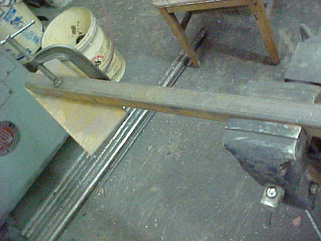
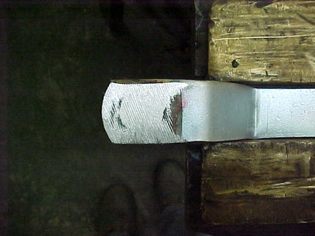
I angled both sides as I have to grind away everything above the shaft so I can remove it if need be.

MVC-023S_1.JPG


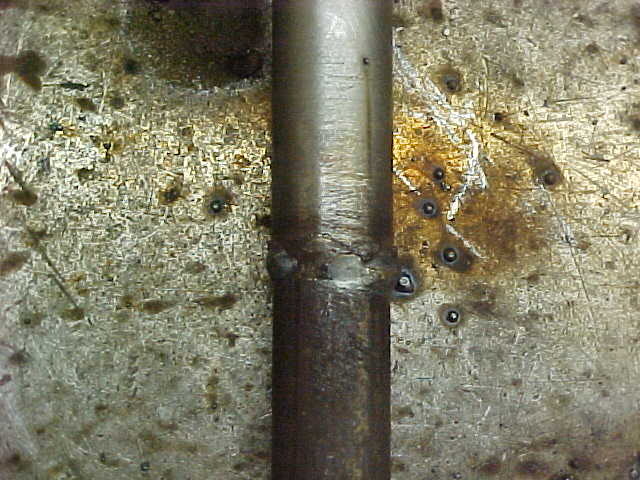
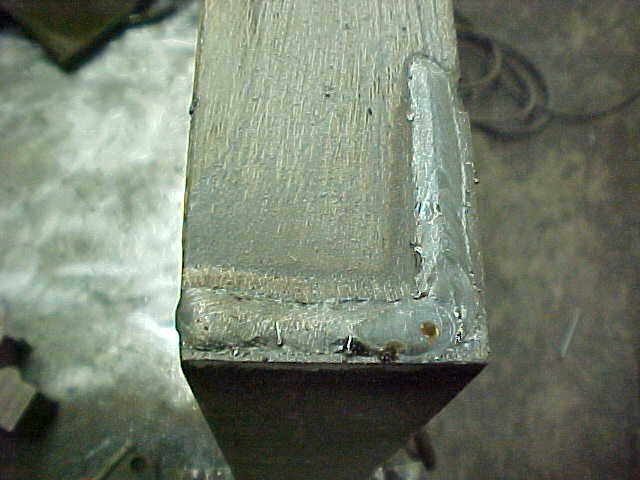
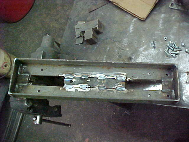
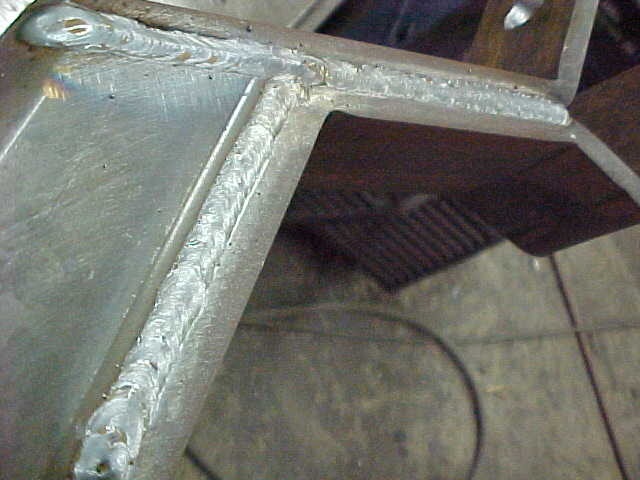
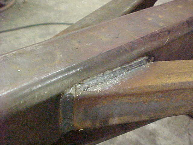
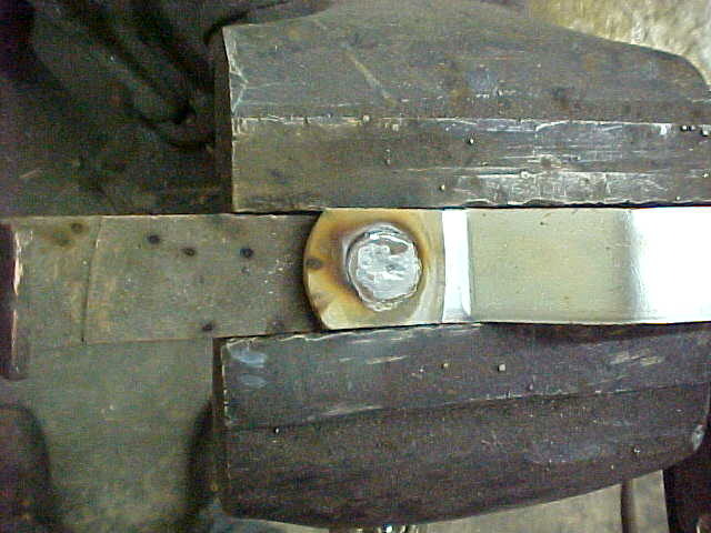
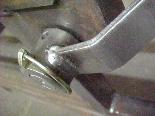
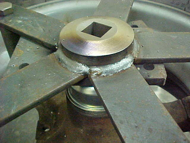
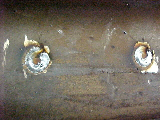
Welded it up with the MIG then I realized I should have just used the TIG as it would have been better. I'll have to smooth this out now.

MVC-001S_18.JPG


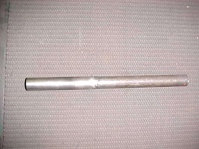
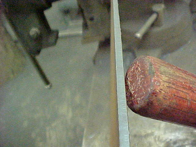
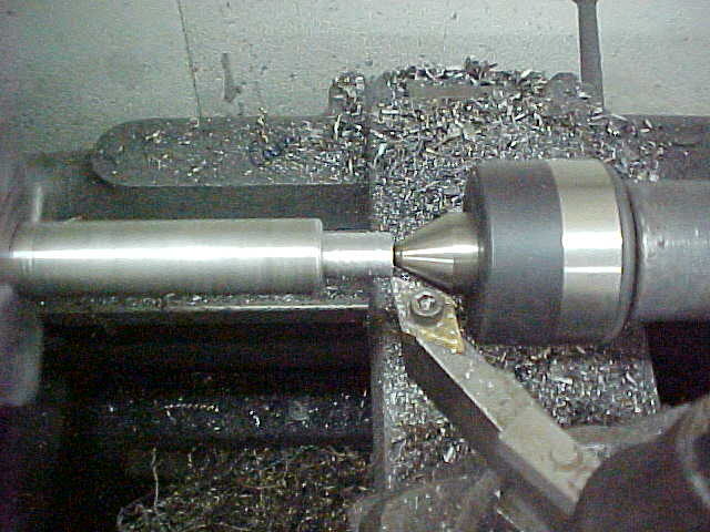
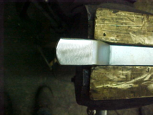
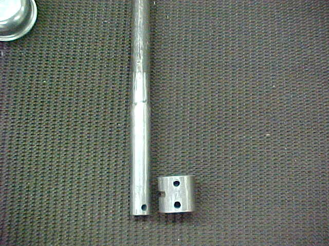
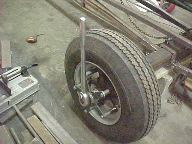
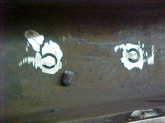
Shaft all smoothed out and blended so it slips right in now.

MVC-002S_18.JPG


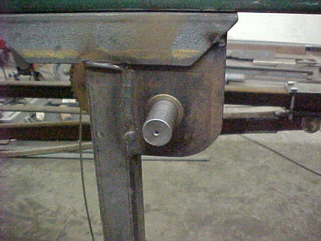
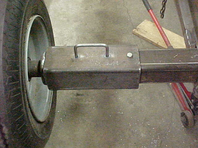
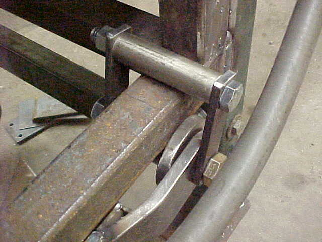
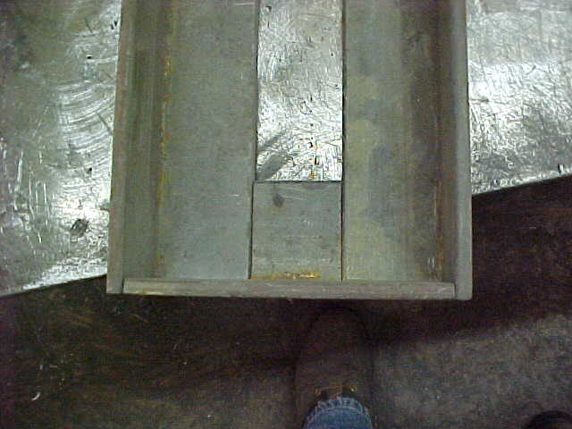
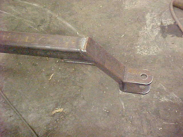
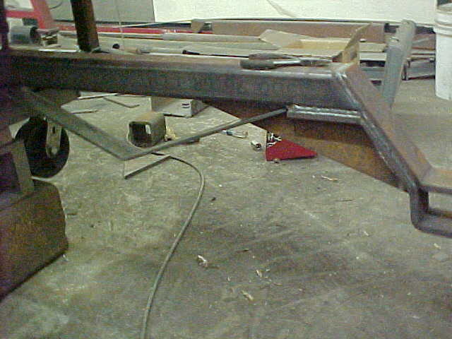
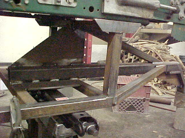
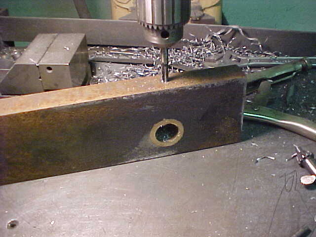
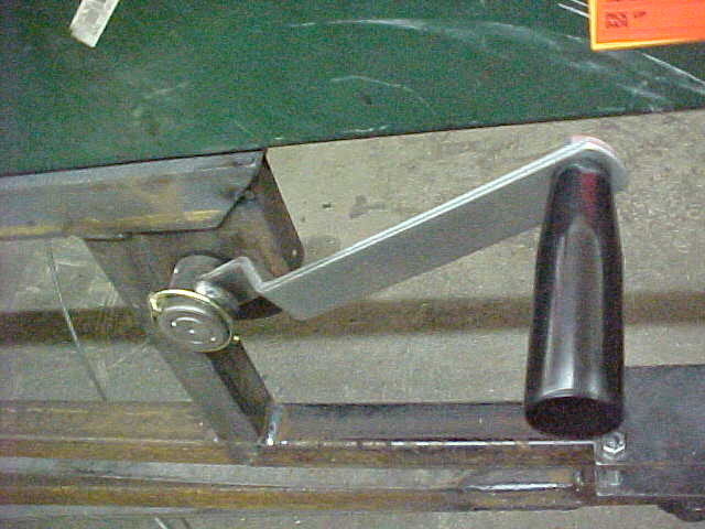
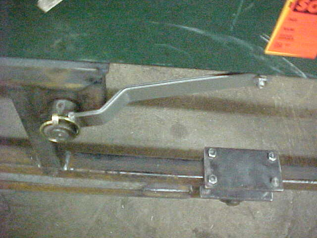
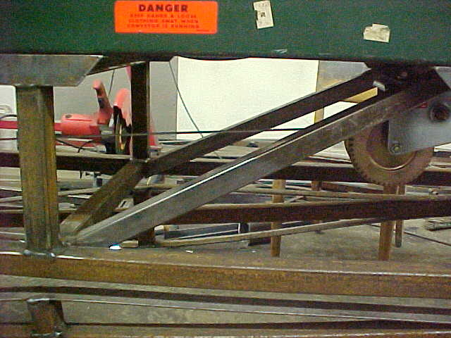
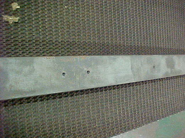
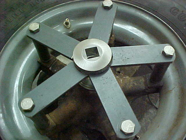
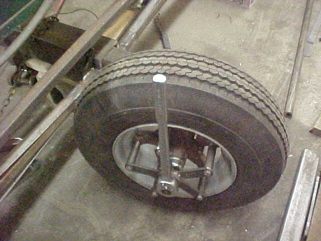
Put the shaft in and made sure it wasn't binding, then I welded the 1 x 3 block in place.

MVC-003S_18.JPG


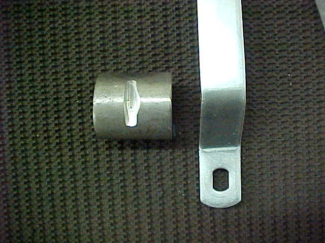
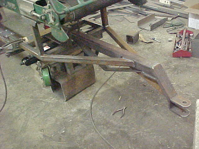
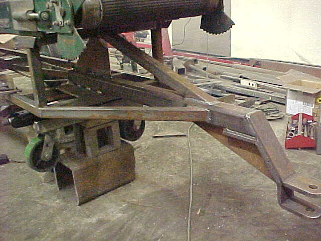
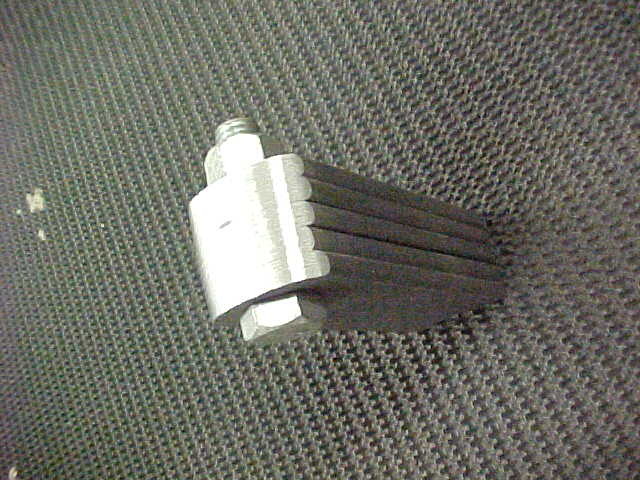
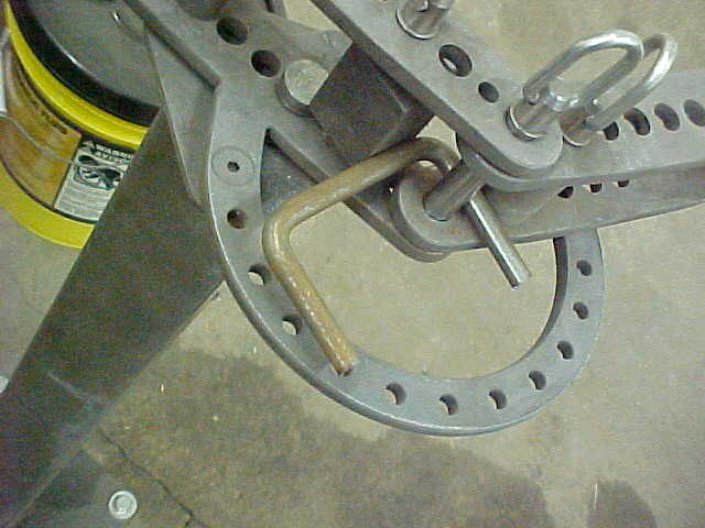
For the crank handle I want to be able to reverse it quickly so it's out of harms way. I cut off some round stock and gouged a slot in it with the chop saw in inset the original handle.
 
MVC-004S_17.JPG


Didn't want to shorten the handle but it had a indexed hole in it. I stuck a piece of heavy copper under it and plug welded it. Weld doesn't stick to copper so it fills the hole quickly with no blow through.

MVC-005S_14.JPG


Ground it close then ran a file over it a few times to get to this point

MVC-006S_14.JPG


Soft pad it a few seconds and "what hole?" ;)

MVC-007S_12.JPG


Carefully marked the holes on the collar so they were equal and in the center. I want to be able to use any of the 4 possibilities and slide a spring pin in. I stair stepped drilled and it brought it all in true.

MVC-008S_10.JPG


Ready to weld it up and will make a nice handle.

MVC-009S_8.JPG


Handle on and done. I triangle filed witness marks on all four possible positions so in a glance you get the pin to drop right in.

MVC-010S_7.JPG


Handle in and out of the way.

MVC-011S_7.JPG


Really like how this turned out and the solid feel of it.

MVC-001S_19.JPG


Put some box tubing on angles to help support the winch assembly.
 
Good. Was not sure how posting that observation would go over. I second guessed posting it after I did so. Thank you. A multipurpose conveyor may be very useful.

How it would go over? I'm always open for tips anyone could give me and appreciate anything you see that may cause issues. Never too old to learn and you just keep building your knowledge/experience base faster that way. Guys have helped me through the years and just trying to pass what I have found along.
 
MVC-001S_17.JPG


Had an idea for making it easier to move the whole conveyor around by myself. I got some 2 1/2" round stock and cut/ground to 1" thick. Wire cut a .760 square into each of them.

MVC-002S_17.JPG


I then put them in the lathe and turned some angle reliefs.

MVC-001S_20.JPG


Got some triple wall pipe and cut 10 pieces to equal length. Then drill and tapped them to 1/2 fine thread. I'll grind some wrench flats on them later.

MVC-002S_19.JPG


I screw them onto the existing wheel studs.

MVC-003S_19.JPG


Laid out some holes on a piece of strap. Need a 1/2 inch hole on one end and a 1.250 radius on the other.

MVC-004S_18.JPG


Drilled the .500 holes and used a 2.500 hole saw to make sides at once.

MVC-005S_15.JPG


Bolted 5 of them together to confirm they were all the same. They fit real nice.

MVC-006S_15.JPG


Rounded the opposite ends so they were all the same.

MVC-007S_13.JPG


I then put the straps on with the center section in the middle. Self aligns and holds it all in place. I cheated old school on the size. Took paper and cut them to the strap width. made a circle with 5 of the and found the center size that was a nominal of a hole saw.
 
MVC-001S_21.JPG


Weld them all up. Then took it off and welded the backside too.

MVC-009S_9.JPG


Now with just a 3/4" ratchet, I can move it around by myself easily. I'll probably shorten the extenders so they don't stick out too much. I wanted to go long at first to see exactly how much I needed to take off.

MVC-010S_8.JPG


Makes for easy wheel turning too.

MVC-003S_20.JPG


Making up the axle locks now. Want it safe for road travel so I'm using heavy box opened to a C to hold it in position. Cut them to length on the chop saw and plasma cut the bottoms open.

MVC-011S_8.JPG


Cleaned up the cuts and rounded the corners. I then decided to make up handles for ease of on and off. Got some 7/16" round stock and bent 2 of them up.

MVC-012S_5.JPG


Drilled the holes in the C's and drove the handles in. I set the depth with some scraps so it would be even on them.

MVC-013S_6.JPG


I had countersunk the holes on the inside and didn't bother with making them the same length.

MVC-014S_5.JPG


I just tack welded them and then cut the excess off with the angle grinder flush. I want this to lay flush on the axle box.

MVC-017S_4.JPG


Then welded the rest home.
 
MVC-018S_4.JPG


Ground them flush again.

MVC-019S_3.JPG


Drilled a pilot hole in the C on the press then hand drilled it to the axle. Stepped up to 1/2 thread size and tapped it for that. Here it is all done. Simple and strong.

MVC-001S_24.JPG


I need to have keepers on the lift/support rails to keep them in place while the cylinder is lifting. I cut 4 pieces of strap to length and will attach them to the rollers after drilling the holes.

MVC-002S_22.JPG


Cut 2 pieces of .875 stainless for rollers and gun drilled them to .500. Could have probably just used the .500 bolts but the larger diameter will roll easier.

MVC-003S_22.JPG


All the pieces are done and ready to try out. Lots of little things to do to make everything work nicer.

MVC-004S_20.JPG


Just what the doctor ordered ;). just enough slop to prevent binding but also tight enough to keep the rollers on the rails when the cable is slacked.

MVC-001S_25.JPG


I want to have wheels on the front as well so I can push it around as a level conveyor table. My Furnace house's floor is higher than the drive so I need to be able to adjust for things. Found this scissor jack and it has 25 inches of adjustment.

MVC-002S_23.JPG


This will also double as the jack when hitching/unhitching so doing 2 things with one. Need this to have some stability so 1/4" angle gets the call. Made it as wide as the conveyor and cut the ends too.

MVC-003S_23.JPG


Got my surface grinder up and running again and for stuff like this it is a great cutting tool. Can cut straight and to the .001 of an inch. I'm notching the ends here to lay flush with the sides. Basically make everything self squaring.
 
MVC-004S_21.JPG


Clean off the paint and it's ready for welding. I'll bevel the edges as well.

MVC-005S_17.JPG


Here you can see how nice of a cut it does.

MVC-006S_17.JPG


Weld it all up and makes for a real strong base.

MVC-007S_15.JPG


Drilled the holes for the casters and the mounting holes that are on the scissor jack. Ready to see if it all fits!

MVC-009S_11.JPG


Fit fine but to get the max out of the jack I decided to relieve the ends about .750. Now I have to decide it position and work out all the variations/options of how I will use it.

MVC-008S_12.JPG


This is the best position for what I want. I will be making the hitch now as well. Wheels will be 8 inches off the ground clear up. Hopefully that is enough or I'll have to make them detachable.

MVC-001S_26.JPG


cut another cross brace out of tubing and welded it in. The Jack mount is about 3/8" from being flush with the tubing so I'll make a mounting plate out of some steel that thickness.

MVC-002S_24.JPG


Cut it out and marked some holes for the mount. Probably won't use these as they are in the way for what I have planned but easiest to get to at the moment. The hitch will come though there.

MVC-003S_24.JPG


With the fold down table on there the hitch has to stick out a good bit. I also have to drop it some so I'll have some gussets and such to do. Just clamping everything for now till I'm happy with what I got.
 
MVC-004S_22.JPG


For the attaching point I got some 1/2" flat stock that's the same width as the box. Need to bend it so I'm using the press. I mark the bend and then use a combo square to make sure it is at 90 degrees.

MVC-005S_18.JPG


Quick and easy. This will be the top of the mount. I'll bend up another for the bottom next.

MVC-001S_27.JPG


Cut it to length and drill an .875 hole. I then bent up the lower to match. I gave it 2 inches in the yoke in case I use the big tractor with it.

MVC-002S_25.JPG


Got it all welded after checking it with tacks. I'll drill the lower hole and round the corners now.

MVC-003S_25.JPG


Clamped back in pace and it's ready for gussets. Sticks a ways out there so it'll need some extra to keep it from bending and such.

MVC-001S_28.JPG


Making up a gusset and here is a little trick for straight cutting small pieces. Put a straight edge in your vise and clamp the piece to that. Keeps everything in the clear and easy to do.

MVC-002S_26.JPG


Welded the tube on as well as the gusset. I bent up a piece that will go under as well but won't weld it on till all the gusset welding is done at tear down. It will have a stand in the middle and I'll stretch it then. Side bracing next.

MVC-003S_26.JPG


Used a sliding T bevel to get the angle I wanted then made one cut. Laid them on top of each other and cut the other ends angles. 2 identical pieces that way.

MVC-004S_23.JPG


Welded those on and that should take care of the side to side stress.
 
MVC-005S_19.JPG


Beginning to take shape. Next I'll get the potential up and down stress/force taken care of.

MVC-001S_29.JPG


Made up another piece of box tubing with angles to support the front and on the rear I drew up a pattern and cut a piece out of some flat stock.

MVC-002S_27.JPG


The plasma really leaves a smooth cut as you can see. Very little work needed after cutting and barely warm to the touch.

MVC-003S_27.JPG


All welded in and looks good to me. May add some gussets later but this will work for set up and rough build.

MVC-004S_24.JPG


Road transport and bouncing are what always cause problems so it's better to be safe than sorry.

MVC-005S_20.JPG


With the adjustable front table it clears fine in the full down position. Don't think I'll ever use it there but it's nice to have options!

MVC-006S_18.JPG


Now I can check how my balance is doing. Front casters seem a little weak as they move a good bit with the scissor jack arms. I would not want the jack to fold under while moving. I think I'll make it a cross with 4 wheels.

MVC-007S_16.JPG


I have over 2 ft of front adjustment so I'll scoot it back as much as possible. This is so I can stick the conveyor in as much as I can before the wheels/axle hits something.

MVC-001S_30.JPG


Added the 2 extra wheels. Won't work when conveyor isn't level but don't plan on using it in that way so it should be a non issue. Put them on and looks/feels a lot better.
 
Im liking this thread way way better than your splitter build thread, that one way frankly a bit disappointing...

Not because the work wasn't awesome or the design or even the colour you chose, I still remember when I first opened it (splitter thread) and was amazed at the time and care that was evident, the only downside was you posted the whole build in one evening and didn't spread it over a few days or even weeks like this one... ha ha
All good though, and this is looking great already, looking forward to seeing it finished and happy to follow at the pace you are posting...

So when are you finding the time to work on it, during shop hours or in the evenings after??

Well, I didn't remeber that. After checking it started Aug 21 and ended Sept 5 according to the thread. Trust me, I'm not that good with a computer. Been working 7 days at the day job and got other stuff going on so it's dragging along. No rush by me, it'll get there. This has taken longer than the splitter! Thanks for the comments too. Building and figuring stuff out is the fun part for me. I normally get about 3 hrs a day on it. Yeah, I don't watch TV too much. ;)
 
As Mr He said, Wire EDM. Can hold .0002" tolerance on the cut size and is a standard in the trade. They can do some pretty wild stuff.. We just always say wire cut.
Man, you have some serious dood toys!
Well, I didn't remeber that. After checking it started Aug 21 and ended Sept 5 according to the thread. Trust me, I'm not that good with a computer. Been working 7 days at the day job and got other stuff going on so it's dragging along. No rush by me, it'll get there. This has taken longer than the splitter! Thanks for the comments too. Building and figuring stuff out is the fun part for me. I normally get about 3 hrs a day on it. Yeah, I don't watch TV too much. ;)
Lots of dood toys, and time...must not be a Mrs KiO...or little KiOs
 

Latest posts

Back
Top