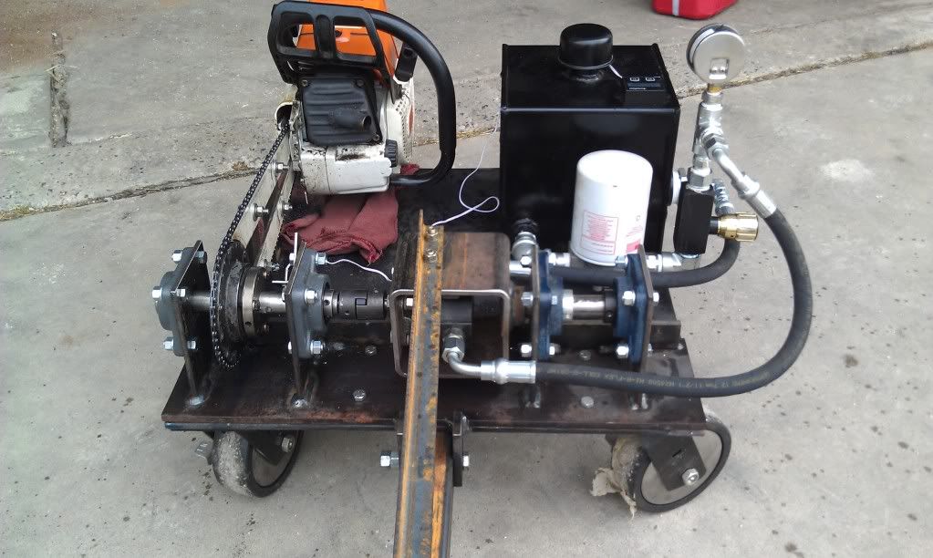
One thing I haven't noticed mentioned that would account for the inaccuracy of the reading, friction and inertia aside, is the increase in temperature of the hydraulic fluid. I've built a few small engine dyno in the past and the simplest is driving a positive displacement pump. Hydraulic pumps are simple and cheap to come by and can stop a very large load. I used have a 400 HP rig that used a 50 HP hydraulic pump out of an old combine. There was only one source of measurement in power and that was a pressure/temp gauge. As the pressure went up rolling resistance was placed on the engine and by calculating the temperature increase of the fluid at a given rpm one could determine work done and torque applied. I cannot for the life of me find the old files I had with the formulas in a spread sheet but know I found them online very easily.
So if you take the fluid temp increase, along with the friction of the chain, slippage in the clutch, resistance of a viscous fluid through the pump, and bearing friction all into account. You should have a very accurate setup. As someone who has spent the last ten years developing import race engines and countless hours of dyno work I must say nice work!

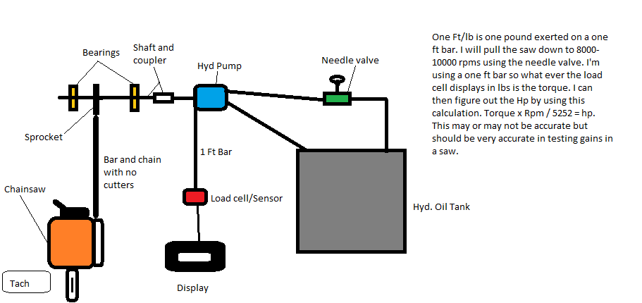
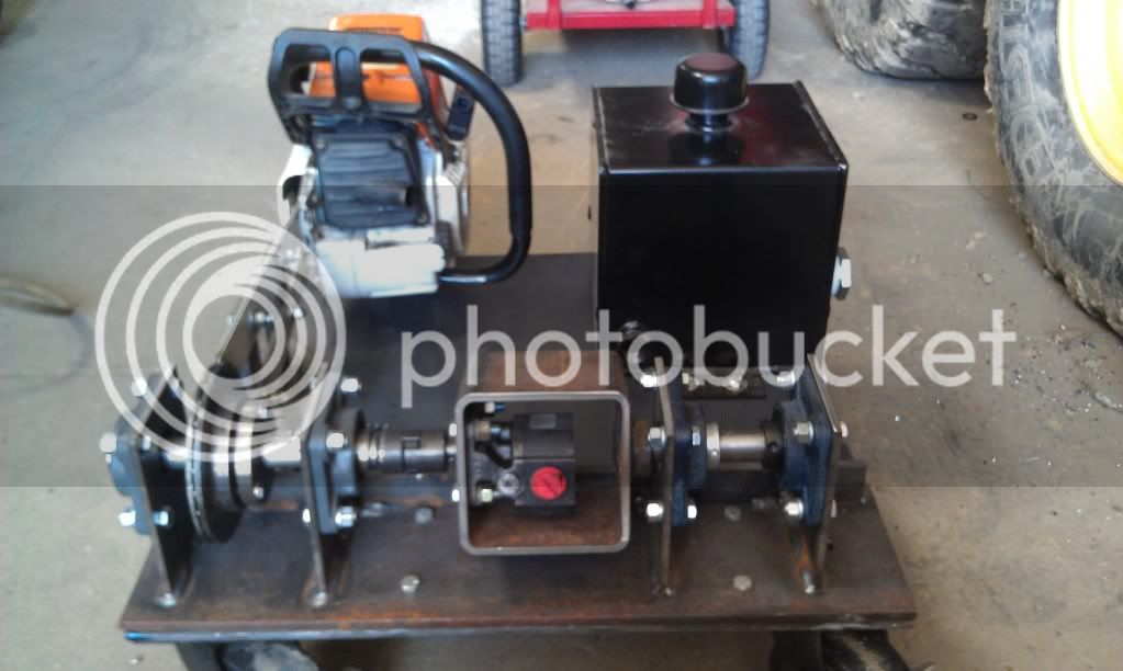
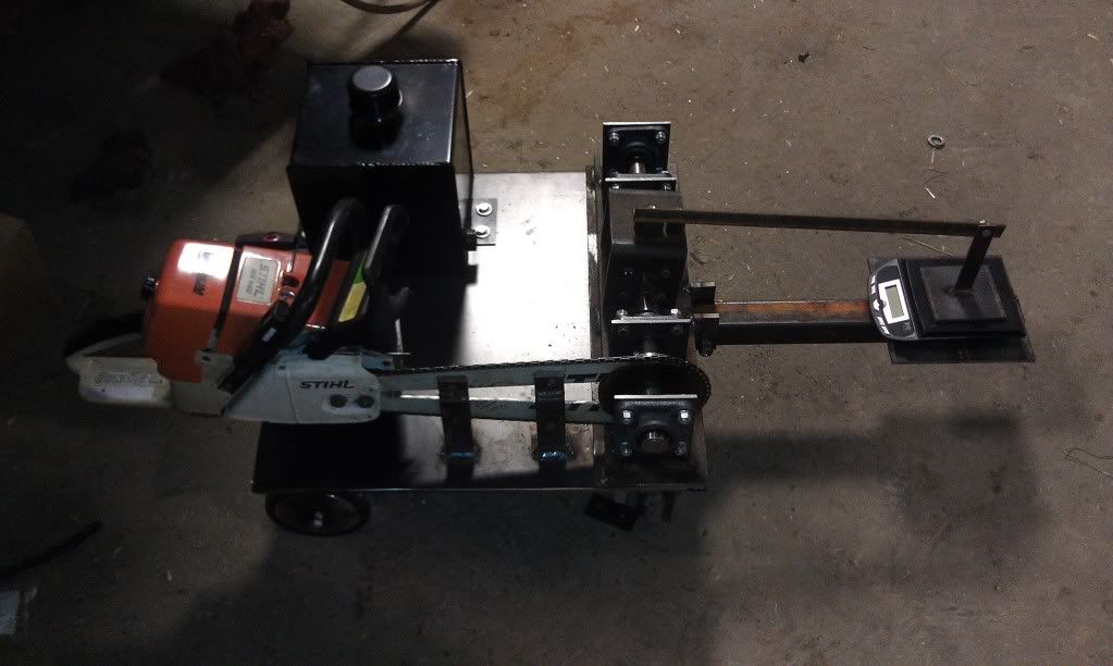
You must have missed the torque arm and scale on this dyno. Change in fluid temperature won't affect the accuracy of the measurement. It will cause difficulty in load control because the viscosity will change and the pressure drop across the regulating valve will drop as the oil heats. This will require adjustment of the valve to maintain constant speed.
I can't imagine using temperature change to calculate dyno load. Pressure and flowrate would do it more accurately.