2 Cycle / 4 stroking question.

Arborist Forum

Help Support Arborist Forum:

This site may earn a commission from merchant affiliate links, including eBay, Amazon, and others.
...
What I hope they may show is that I may have overstated the problem of lean out under increased load - perhaps at typical load airflows the curve is flat enough that this effect is not that extreme. However, as these particular runs were apparently to explore the peak HP/torque, it would not have focused on exploring higher loads that bog the engine more.

That run was to characterize the performance of that engine through all normal operating ranges with emphasis on AFR, emissions, and BSFC. Since it seems you are new to reviewing this type of data it's a bit presumptuous to tell me what my goals were when I ran these tests.

There's no need to load the engine to any lower speeds because at 4500 it's well below peak torque and a chainsaw won't run down there. It takes a smooth hysteresis brake and digital controller to modulate the load and maintain speed at those points. Put a chainsaw in wood, start to cut at max power, and push on it. It pushes back--you are on the right side of the torque peak; if the chain drags the engine speed down the torque increases and pulls the chain harder. Dog it down past the torque peak and the saw goes 'bluuuuuuuhhhhhhhh' and stalls or slips the clutch. On the left side of the torque peak if the engine loses a few rpm there's even less torque to pull the chain and it slows down more--dropping torque further. Sure, you could pull it out of the cut and speed back to torque peak--but there's no way you're going to run the saw below peak torque for more than seconds. So the data presented covers all necessary loads.
 
Here are some more plots from the same run to look for a correlation between air velocity and fuel flow.

8TV8K.jpg


nZwlD.jpg


cgQAS.jpg


uS21Z.jpg
 
Mostly for WHW, I'm going to post again about the RPM/mixture relationship because I think when you scrutinize your assumptions about fluids, you'll agree, or maybe agree to disagree less about agreeing.
........

Anyway, on to experiments if you want to talk about one. I thought more about it. What we need would function similarly to an analog, full-RPM-range automatic choke controlled by the pressure differential between venturi and atmosphere. I think Stihl's "intellicarb" is a tiny and somewhat roundabout step toward this answer

.........

What do you think?
Fluid dynamics was an elective I opted out of - and would again! Stihl's "intellicarb" is just connecting the diaphragm vent to downstream of the air filter rather than direct to the atmosphere. SOP for most things for decades. As for mods and experiments to linearize the fuel delivery, that problem was solved long ago via air corrector jets on fixed jet carbs or by using a CV carb with needles. Now with AutoTune coming in it seems like a wasted effort at this point. I may drill an air corrector in an old Walbro WT some day if I ever have time to play, but you'd first have to calculate the effective H jet size with the needle properly set, which would be a bit difficult.

That run was to characterize the performance of that engine through all normal operating ranges with emphasis on AFR, emissions, and BSFC. Since it seems you are new to reviewing this type of data it's a bit presumptuous to tell me what my goals were when I ran these tests.

There's no need to load the engine to any lower speeds because at 4500 it's well below peak torque and a chainsaw won't run down there. It takes a smooth hysteresis brake and digital controller to modulate the load and maintain speed at those points. Put a chainsaw in wood, start to cut at max power, and push on it. It pushes back--you are on the right side of the torque peak; if the chain drags the engine speed down the torque increases and pulls the chain harder. Dog it down past the torque peak and the saw goes 'bluuuuuuuhhhhhhhh' and stalls or slips the clutch. On the left side of the torque peak if the engine loses a few rpm there's even less torque to pull the chain and it slows down more--dropping torque further. Sure, you could pull it out of the cut and speed back to torque peak--but there's no way you're going to run the saw below peak torque for more than seconds. So the data presented covers all necessary loads.
LOL - this is not my field but it's hardly the first HP/torque curve I ever saw, which is why I used the term "bogging", but thank you for the description. You've limited your analysis to "all normal operating ranges", which is why it doesn't cover WOT no-load, light load or bogging the engine below the useful output range, all of which happens to real saws.

I made the statement that an uncorrected fixed jet will yield a fuel/air ratio that is approximately the square of the air velocity, and from that roughly the square of the rpm at WOT, and that without the air corrector jets a chainsaw carb will have that characteristic. This happens to match the known characteristics of 4-stroking, setting setting AFR at no-load WOT max rpm, and engines that suffer lean damage when the operator pushes on (loads) them excessively. You took me to task on that but have not addressed any of these issues, what function the air correctors perform or what impact removing them has. You've essentially said that the no-load WOT max rpm is not primarily a function of AFR and may not be predictable, but don't say why manufacturers set fuel mixtures there. Your data is restricted to normal operating conditions and does not cover any of these abnormal conditions.

As to this normal operating range bit: If I design a power supply then it must perform to the advertized spec over the normal operating range. But even outside of the normal operating range, if those conditions are likely to occur then the thing darn well better not fail when it happens. People shouldn't bog saws, but they will. What happens to the AFR?

I'm a bit less concerned now about lean out at lower rpm - it may be that the curve is flat enough down there that it isn't a big problem, but it would require analysis of those conditions to really tell. Other than that this has moved past the point of fruitful discussion and taken on an unpleasant undertone, so I will stop here.
 
Last edited:
... People shouldn't bog saws, but they will. What happens to the AFR?

I have presented the AFR data for an engine bogged to a speed that can not be reached by a chainsaw and explained that in the text you quoted.

I have presented fuel rate and air flow data that shows there is not a velocity squared correlation.*

There's no point in discussing this further.

*edit: After a little number crunching I realize I'm wrong--the data presented does show a second-degree relation between air flow and fuel flow. I'll leave it to others to find that relationship.
 
Last edited:
I guess I'll have to assume that as an engineer with access to dyno runs of trimmers, blower and chainsaws, and with a desire to defend the defend the industry that you probably work in that industry. I apologize if I have offended.

Come on man, you shouldn't try to stick an agenda accusation to a guy who is posting data. And so what if he works in that industry? Those plots stand to show you that this is a misunderstanding:

You have stated that the fuel/air ratio is not a squared function of airflow as I claimed, that it may get leaner or richer, and that max no-load WOT rpm is not due to a squared function mixture becoming terminally rich, but rather due to several other causes.

Liquid fuel flow into a venturi is a function of a pressure differential inside a carburetor barrel. That differential assumes the square of air velocity, and so fuel flow is related to velocity as a squared function. Air/fuel RATIO is not a squared function of air velocity. And the relationship of RPM to air/fuel ratio is yet another degree of separation, which introduces a lot of chaos, it's true. RPM to AFR is what the plots demonstrate. The plots are easy to interpret.

Most every manufacturer specifies a max no-load WOT rpm for purposes of setting the fuel mixture at lower rpms under load - it is an otherwise meaningless operating point. This confirms that there is in fact a consistent relationship between that terminal rpm and the fuel mixture under load, or it would be pointless.

Manufacturers also call this "max permissible RPM," which is self-explanatory in its having a "point" other than determining mixture at intermediate RPMs and loads.

Your plots do not show that region, nor do they show an engine 4-stroking which we know they do. This is not surprising as they appear to be runs to determine max HP/torque curves, not light load at all.

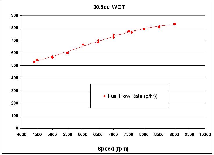
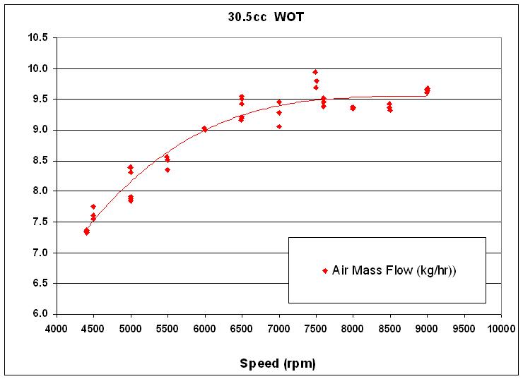
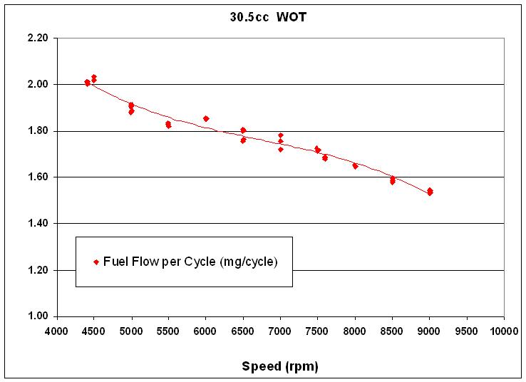
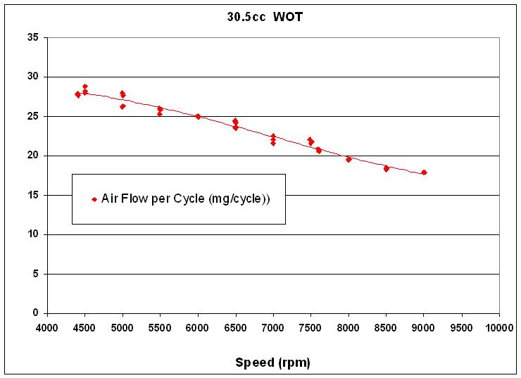
They show intermediate RPMs for WOT, and the explanation for those RPMs' not being WOT-max is load, because mixture is included as an axis and is clearly not the RPM limiter in this range. Whether or not mixture is the ultimate limitation doesn't matter to the relationship shown. So the plots show what we've been talking about. How often do you get data like that on a forum, man? Perk up.

Fluid dynamics was an elective I opted out of - and would again!

What is that supposed to mean? Yes, in this thread I see that you don't think fluid dynamics is relevant. But the squared relationship you've married is derived directly from either of Bernoulli's equations. I'm crying here, literally crying a river of fluids trying to show that more details about fluids matter critically to this question, and temper the relationship you're concerned about -- a relevant one, we've been saying all along.

Stihl's "intellicarb" is just connecting the diaphragm vent to downstream of the air filter rather than direct to the atmosphere. SOP for most things for decades. As for mods and experiments to linearize the fuel delivery, that problem was solved long ago via air corrector jets on fixed jet carbs or by using a CV carb with needles. Now with AutoTune coming in it seems like a wasted effort at this point. I may drill an air corrector in an old Walbro WT some day if I ever have time to play, but you'd first have to calculate the effective H jet size with the needle properly set, which would be a bit difficult.

But you started this discussion by saying that existing carbs are lame for lacking what I now understand to be correction, and because we don't know of either not-lame carb design being available for saws, I was asking to see if you thought it would be feasible to modify a carb to mitigate the variable mixture problem (which exists, but isn't as you have described). Why don't you experiment with correction on the WT and see if its general result is reducing the mixture/RPM trend? That would be proof of concept; I for one am interested. I understand the function of the intellicarb design. I'd like to try this experiment, but I think I know less about carburetor designs than you fellas do. I can tell you with some confidence what the modifications should do, but I have little knowledge of what historical carburetor designs have included and what unexpected things have accompanied those designs, etc.

I'm a bit less concerned now about lean out at lower rpm - it may be that the curve is flat enough down there that it isn't a big problem, but it would require analysis of those conditions to really tell. Other than that this has moved past the point of fruitful discussion and taken on an unpleasant undertone, so I will stop here.

Those conditions are shown in the plots.

Nah, there's no unpleasant undertone here. You've not been taken to task for your claim that there's a variable mixture issue or that there's a square somewhere in the mix. Your assumptions linking the air velocity / liquid movement relationship to a putatively identical RPM/mixture relationship, and to the handful of conditions you've described (four-stroking, RPM limitation at WOT, etc.), are just being challenged. BTW, I think the motivation for the challenge is to say "don't worry, it's not as bad as you're saying." Still a discussion full of fruit.

You don't even have to take my word for anything, just run some numbers: if the relationship even approaches a situation where MIXTURE RATIO changes as the square of RPM, then you can see just how much different AFR would be at WOT 10K vs. WOT 11K RPM in a saw if it's RICHNESS LIMITED to 11K at UNLOADED WOT. It doesn't have to be all the way to square -- a concave-up function with much curvature will do.

Now, pleasantly undertoned about the fruit:

How and where will you drill your WT? You're talking about adding a jet to the fuel delivery carb inlet, which is what a corrector jet is, right? Not adding an air inlet to the venturi, which has been what I've been trying to think about?

I've been thinking about how the air valve in a strato engine should flatten the mixture/RPM relationship like you were saying. It should have that general effect, and very generally, any small leak in the stream delivering fuel fluid from venturi to combustion chamber should have the effect of flattening the relationship. It flattens them to "too lean everywhere, saw cooked" when uninvited, but it ought to be easy enough to see if experimenting with the idea can lead to a saw that leans LESS when loaded.
 
OK Torquey Todd, one last just to better illustrate how the air corrector works:

attachment.php


IIRC on most Weber setups the air corrector jet is typically larger than the fuel jet.
 
2cycle stroking

When someone is stating their 2 cycle engine is 4 stroking, what exactly are they referring to? A 2 cycle has a compression and an exhaust stroke so whats going to make this happen or what sound is occurring. Is it just the sound of the engine laboring when running to rich at idle or what?

Maybe its something Ive incurred before but not familiar with the terminology of so help a dummie out here.

Been around Chain saws as long as I've been around cars. Best I've ever seen ( thats worked flawlessly was a customer upgraded a metering orifice on an old 16" craftsman. Ate a lot more fuel,plugs , chains and chain oil but lasted 15 yrs. This guy did about 6 cords per season. Like to know myself what they did to "stroke " the engine.
 
were the graphs removed? i do not see a graph or a link. oh well would have liked to see those plots.

You've essentially said that the no-load WOT max rpm is not primarily a function of AFR and may not be predictable, but don't say why manufacturers set fuel mixtures there.

from what i learned: carbs on 2 strokes behave differently than carbs on 4 strokes. the max/min pressure fluctuations from atmospheric to below are much smaller in a 2T motor than in a 4T. the pressure fluctuations within the motor affect the AF to a large degree, (along with RPM and inlet length). when a motor is at max capable RPM, the pressure differntial within the the motor becomes closer to atmospheric, and connot draw the proper amount of fuel through the carb due to this loss of vacuum. time area of ports cannot keep up with the RPM. why do manufacturer's set fuel mixtures there? assume it would be to ensure that there is a strong enough AF ratio to work at all RPM's below the max capable RPM the saw can run at.

there are more techniques that can be used to tune a saw than this anyway. the "4 stroking" technique is a popular one.
 
OK Torquey Todd, one last just to better illustrate how the air corrector works:

IIRC on most Weber setups the air corrector jet is typically larger than the fuel jet.

Thanks. I am going to try and learn about Weber carburetors, and probably be back with a couple of questions, and then I'll try to do something productive with a WT I have that can be sacrificed for this purpose. I can't add a jet, but I think I can add an inlet elsewhere that will do something similar.
 
could you explain this point further? i have never heard that term used.

from what i gathered, RPM potential is based on charge density.

-OMB

drkptt referenced some RPM-limiting factors other than mixture. WHW used the word "chaotic" to describe drkptt's explanation of these factors. I was trying to say that though WHW's description of liquid fuel flow rate into a venturi is theoretically as he has stated (the former the square of the latter), that theory doesn't apply for a relationship between RPM and mixture. I meant to point out that what breaks that linkage is the violation of assumptions underlying the first relationship -- frictionless laminar flow expecially.

What you've said sounds consistent with that, to me. Small holes and friction, limiting how much charge of any density can be delivered per time. My understanding is that increased limitation as RPM increases must offset the RPM/mixture relationship. Obviously I don't know the extent, and imagine it's highly variable between saws.

I think WHW's point that these carbs ought not to bring about leaning of mixture under load is a good one, and I'm interested in it. I don't think it's as bad as he says it is, and I've been being a pedant in this thread to argue about it. But there's nothing categorical about the argument, just a matter of how bad the mixture variation is to a saw. drkptt's plots show that badness isn't a two-cycle rule, but it does seem like it's a saw rule. The plots also show that fuel pumping efficiency is not constant, which is a pretty big thing to add to this mix-up of stuff.
 
OK Torquey Todd, one last just to better illustrate how the air corrector works:
IIRC on most Weber setups the air corrector jet is typically larger than the fuel jet.

i think what you are calling the air corrector.... is an emulsifier tube. if i understand it's funtion correctly, it was used to help atomize fuel droplets.

i have not fooled with theses carbs, other than seeing quite a few laying around at motor cycle swap meets in the late '80's.

in the '90's a company came out with a brass emulsifier tube which could be pressed in over the main jet outlet for a few different brands of MC carbs. cannot remember the name.
 
Thanks. I am going to try and learn about Weber carburetors, and probably be back with a couple of questions, and then I'll try to do something productive with a WT I have that can be sacrificed for this purpose. I can't add a jet, but I think I can add an inlet elsewhere that will do something similar.

mcCulloch had a carb design in the '60's or '70's which had a circuit added to help with the idea that you are describing. it was called the 'duckbill' circuit. an air bleed which went from the dry side of the diaphragm, into the carb throat venturi. it tricked the carb into delivering more mid-range fuel. from what i've read, some kart racers modified it with small changable air jets to help move the fuel curve from mid-range to higher RPM.

good luck with the experiment. hope that helps.

-OMB
 
i think what you are calling the air corrector.... is an emulsifier tube. if i understand it's fucntion correctly, it was used to help atomize fuel droplets.

i have not fooled with theses carbs, other than seeing quite a few laying around at motor cycle swap meets in the late '80's.

in the '90's a company came out with a brass emulsifier tube which could be pressed in over the main jet outlet for a few different brands of MC carbs. cannot remember the name.
No, the emulsifier tube is the part that sits between the fuel and air jets and helps to mix the fuel and air coming from the two jets evenly. On a Weber the fuel and air jets are attached at either end of the emulsifier tube into an assembly that can be unscrewed. Most street carbs have similar parts but they are not always removable nor in a central location that way. The idle circuit often has its own fuel and air corrector jets.

The "emulsified" fuel & air mixture is not a constant with pressure drop - it gets relatively more air as the pressure difference increases (because it pulls air through the air corrector jet more easily than it does fuel through the fuel jet). That is how it corrects for the non-linearity, and how you control that by changing the relative sizes of the air and fuel jets.

Now consider what would happen if you simply removed the air corrector.

so......#11 is the air bleed jet, and the emulsion tube is under it in the diagram above.

in the weber, moving air through the air bleed pushes the fuel through the emulsion tubes holes. (blowing through a straw).

if that's correct......the weber works in reverse, in operation to the emulsion tube i am familiar with, if i am understanding your explanation above.

in the carb with emulsion tube that i am familiar with, the amount out fuel flow out of the emulsion tube holes is regulated by the air bleed. but in this case, the air is pulled through the air bleed at a controlled rate because the emulsion tube is located in the venturi, and the air bleed is located outside the carb body. (like letting your finger off the end of a full straw).

-omb
Actaully the Weber doesn't work any differently from, say, a MotorCraft 2150 (at least until they put rods in the air bleeds). The air correctors go to outside the carb body, the same pressure that is pushing on the fuel bowl. So when air flow through the venturi causes a pressure drop relative to that external point, then air flows through the air corrector jets and fuel flows through the fuel jet.

If that presure drop increases it will pull relatively more air than fuel because the air has less resistance to flow. This is what coounteracts the natural curve of an uncorrected fixed jet & fixed venturi.
 
For the record -- still hacking up a carb to see if a caveman can install an air corrector in a Zama carb with a drill.

A tiny opening communicating barrel to atmosphere makes the engine run as though it were under a bit more load through RPM range. I had to block off air box to some degree because the Zama carb in question is the fixed-jet unit I displaced from an MS180 and I can't richen the mixture otherwise.

I get the impression that someone who isn't a caveman could do this right, very easily, in an all-position carb. That is, make one with an all-position corrector jet. Messing with it, I gather that it obviates my ability to tune by ear, which I rely on to compensate for fuel and weather variation. That makes for a tradeoff that I might not be willing to make.

Did you experiment with anything, WHW?
No - I doubt I will ever have the time for that experiment. First you would need to calculate the effective jet area of the H side to get a ballpark idea of how large and air corrector you would need. That might be easier to measure on a fixed jet carb but I would not try it without an adjustable H. I do have access to tiny drills here at work.

I strongly suspect the screw in this video is an adjustable air corrector: http://www.arboristsite.com/chainsaw/222290-5.htm#post4132620
 
this site is really gittin expensive now!

i recon now i gotta buy a dynomometer and a 5 gas analyzer to cut firewood.:bang:
 
Back
Top