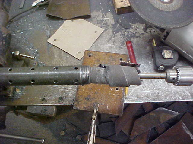
I would disagree with the dispersion tube idea. Every one of those holes is a point where air can be mixed in with the hydraulic fluid and will actually make things worse. The proper way to do it is to have a large diameter (4+") vertical tube inside the hydraulic tank, and have the fluid go in to that at a tangent so it swirls around the inside wall, thereby giving up any air that is entrapped. Holes at the bottom of the tube let the fluid flow out into the rest of the tank.
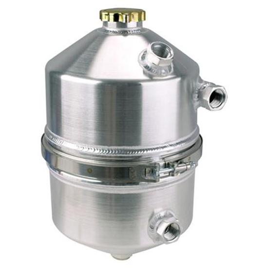
This is how dry sump oil system tanks are made for race cars that need to remove air from the oil whipped around by the crankshaft that is picked up by the scavenge pump and sent to the oil tank before going back to the high pressure oil pump.
Look at this and notice how the incoming oil fitting on the right comes in off to one side and will shoot the oil on to the inside wall causing it to spin around inside as it falls down. A simple large round tube with an open top and bottom would work fine and accomplish the same thing.


")


