hseII
Addicted to ArboristSite
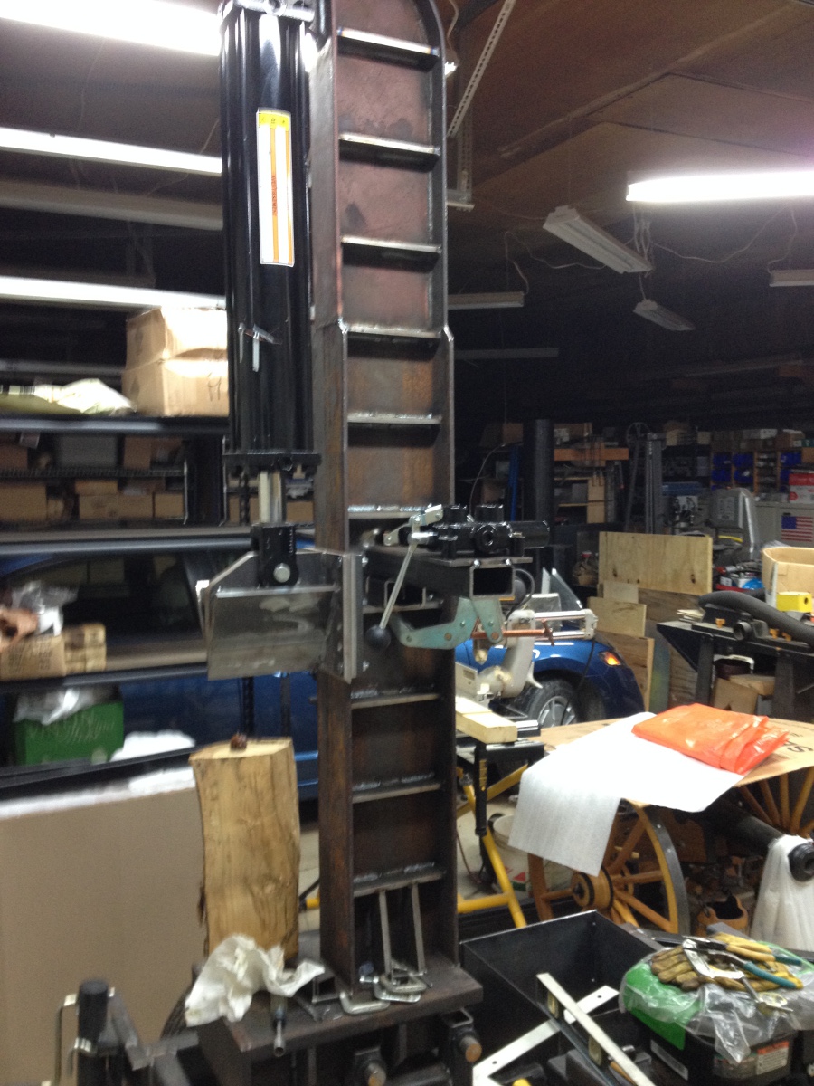
Nice Fab Work. I really like the Gussets along the Beam.
I've got a few Questions:
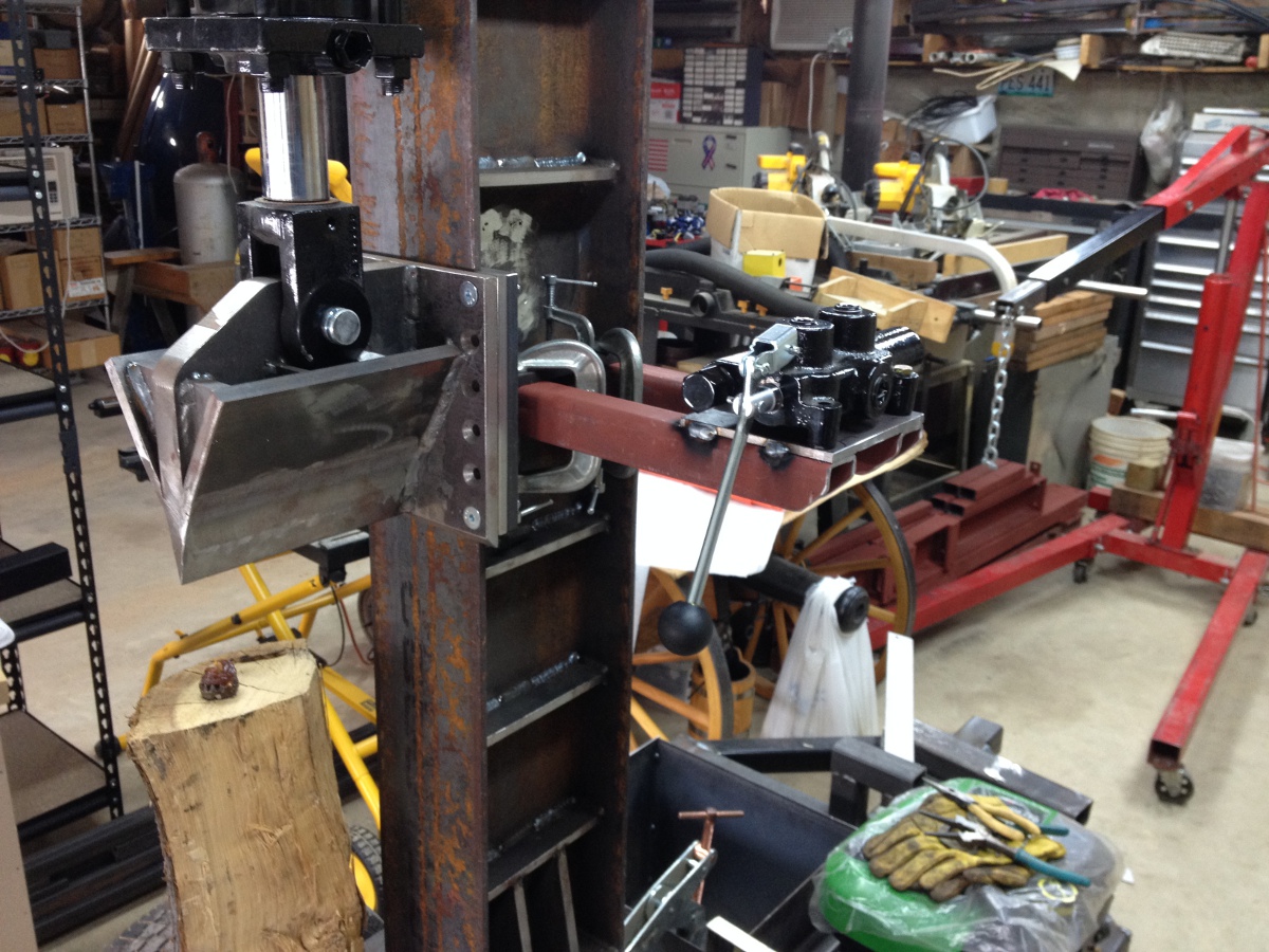
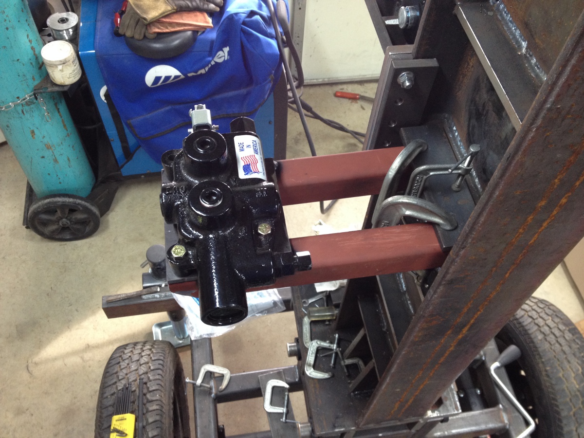
1) What kind of shielding/guard ideas will you incorporate to protect that pump?
Hopefully nothing will ever get that high but now would be the time to address that.
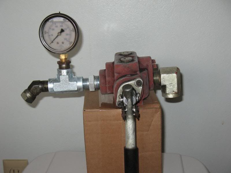
2) Why not mount your valve in the horizontal on a stub up of the material you built the frame out of with a piece of plate on top as the base?
3)will you only be splitting smaller wood,(< 12")?
I don't mean to sound smart, but it would look to be a chore to load larger wood onto you splitter.
I'm sure you've put countless hours in the design of this splitter, and it does look good thus far.
We're going to build a new splitter soon and are discussing which direction we will be going. We are considering building a diesel powered horizontal with a loading gate for the big sections, as we already have a 3 point hitch horizontal unit that Dad and my uncle put together one winter at the fab shop 20+ years ago.
We saved a 10" H beam from some job done in the past and granddad had the local hydraulic shop fab is a cylinder just for the upcoming splitter.( He had this done probably 5-6 years ago, we just haven't got around to putting it together) My 78 yr old grandfather told me the other day that if he could hire,") 3 welders for about 3 days, we'd have us our new splitter.
3 welders for about 3 days, we'd have us our new splitter.
He's a Card
I've got a few Questions:
1) What kind of shielding/guard ideas will you incorporate to protect that pump?
Hopefully nothing will ever get that high but now would be the time to address that.
2) Why not mount your valve in the horizontal on a stub up of the material you built the frame out of with a piece of plate on top as the base?
3)will you only be splitting smaller wood,(< 12")?
I don't mean to sound smart, but it would look to be a chore to load larger wood onto you splitter.
I'm sure you've put countless hours in the design of this splitter, and it does look good thus far.
We're going to build a new splitter soon and are discussing which direction we will be going. We are considering building a diesel powered horizontal with a loading gate for the big sections, as we already have a 3 point hitch horizontal unit that Dad and my uncle put together one winter at the fab shop 20+ years ago.
We saved a 10" H beam from some job done in the past and granddad had the local hydraulic shop fab is a cylinder just for the upcoming splitter.( He had this done probably 5-6 years ago, we just haven't got around to putting it together) My 78 yr old grandfather told me the other day that if he could hire,
3 welders for about 3 days, we'd have us our new splitter.He's a Card